")
| What You NEED To Do |
| Steps of a Lockout Tagout program include: Prepare for Shutdown, Notify All Affected Employees, Equipment Shutdown, Isolation of System From Hazardous Energy, Dissipation (Removal) of Residual or Stored Energy, Lockout Tagout, Verify Isolation, Perform Maintenance or Service Activity, Remove Lockout Tagout Devices. Download a model LOTO procedure that you can quickly edit and make your own. |
Lockout and tag out processes involve more than putting a lock on a switch. They are comprehensive step-by-step processes that involve communication, coordination, and training.
Affected person – persons who are not directly involved in the work requiring the hazardous energy control, but who are (or may be) located in the work area.
Authorized person – a person who is qualified to engage in hazardous energy control because of knowledge, training, and experience and has been assigned to engage in such control.
Steps of a lockout tagout program include:
1. Prepare for Shutdown
1. Prepare for shutdown
The authorized person will identify which sources of energy are present and must be controlled; and more importantly, identify what method of control will be used. This step involves completing sets of specific work instructions that outline what controls and practices are needed to lock and tag out a system before performing any activity.
2. Notify All Affected Employees
2. Notify all affected employees
The authorized person will communicate the following information to notify affected persons:
- What is going to be included for lockout tagout.
- Why it is going to be included for lockout tagout.
- For approximately how long will the system be unavailable.
- Who is responsible for lockout tagout.
- Who to contact for more information.
3. Equipment Shutdown
3. Equipment Shutdown
If the system is operating it should be shutdown in its normal manner. Use manufacturer instructions or in-house work instructions. Equipment shutdown involves ensuring controls are in the off position, and verifying that all moving parts such as flywheels, gears, and spindles have come to a complete stop.
4. Isolation of system from hazardous energy
4. Isolation of system from hazardous energy
The exact written instructions will be specific to that system in the workplace. In general, the following procedures are used:
- Electrical energy – Switch electrical disconnects to the off position. Visually verify that the breaker connections are in the off position. Lock the disconnects into the off position.
Figure 1: Electrical lockout
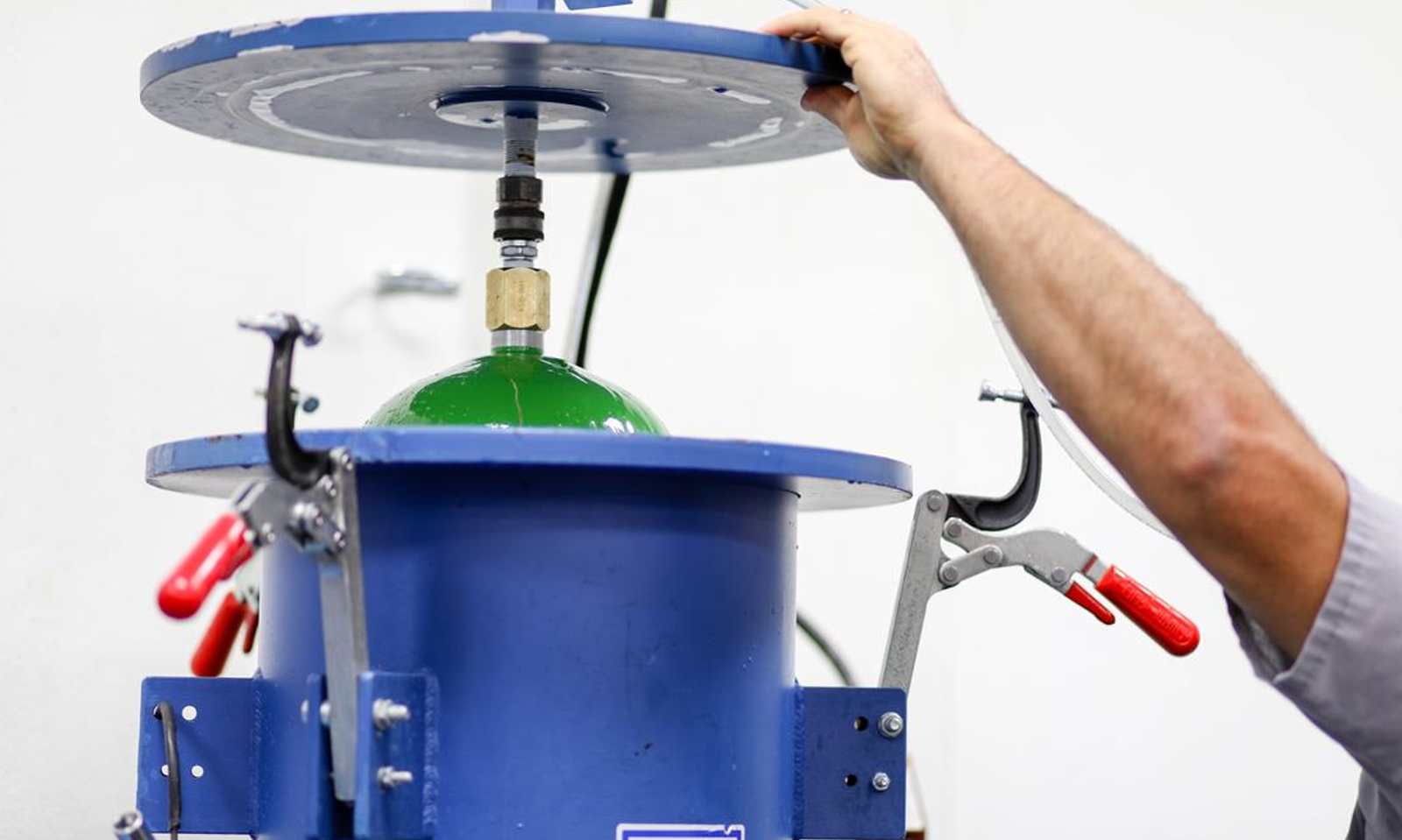
- Hydraulic and Pneumatic potential energy – Set the valves in the closed position and lock them into place. Bleed off the energy by opening the pressure relief valves, then closing the airlines.
Figure 2: Hydraulic and Pneumatic lockout
- Mechanical potential energy – carefully release energy from springs that may still be compressed. If this is not feasible, block the parts that may move if there is a possibility that the spring can transfer energy to it.
- Gravitational potential energy – Use a safety block or pin to prevent the part of the system that may fall or move.
- Chemical energy – locate chemical supply lines to the system and close and lockout the valves. Where possible, bleed lines and/or cap ends to remove chemicals from the system.
5. Dissipation (removal) of residual or stored energy
5. Dissipation (removal) of residual or stored energy
In general, examples include:
- Electrical energy – To find a specific method to discharge a capacitor for the system in question, contact the manufacturer for guidance. Many systems with electrical components, motors, or switch gears contain capacitors. Capacitors store electrical energy. In some cases, capacitors hold a charge and may release energy very rapidly (e.g., similar to the flash of a camera). In other cases, capacitors are used to remove spikes and surges in order to protect other electrical components. Capacitors must be discharged in the lockout process in order to protect workers from electrical shock.
- Hydraulic and Pneumatic potential energy – Setting the valves in the closed position and locking them into place only isolates the lines from more energy entering the system. In most cases, there will still be residual energy left in the lines as pressurized fluid. This residual energy can be removed by bleeding the lines through pressure relief valves. Verify depressurization or use flange-breaking techniques. Contact the manufacturer for more specific details, or if no pressure relief valves are available, what other methods are available.
- Mechanical potential energy – Carefully release energy from springs that may still be compressed. If this is not possible, use blocks to hold the parts that may move if the energy is released.
- Gravitational potential energy – If feasible, lower the part to a height where falling is impossible. If this is not possible, contact the manufacturer for guidance.
- Chemical energy – If available, bleed lines and/or cap ends to remove chemicals from the system.
6. Lockout Tagout
6. Lockout Tagout
When the system’s energy sources are locked out, there are specific guidelines that must be followed to make sure that the lock cannot be removed, and the system cannot be inadvertently operated. These guidelines include:
- Each lock should only have one key (no master keys are allowed).
- There should be as many locks on the system as there are people working on it. For example, if a maintenance job requires 3 workers, then 3 locks should be present – each of the individuals should place their OWN lock on the system. Locks can only be removed by those who installed them, and should only be removed using a specific process – see step 9 below.
Figure 3: Example of multiple locks on a lockout tag
7. Verify Isolation
7. Verify Isolation
Verify that the system is properly locked out before beginning any work. Verification can take place in several ways:
- The machine, equipment, or process controls (push buttons, switches, etc.) are engaged or activated and the result is observed. No response means isolation is verified. Return controls to the safe position (off).
- Visual inspection of:
- Electrical connections to make sure they are open.
- Suspended parts are lowered to a resting position or blocked to prevent movement.
- Other devices that restrain machine or process movement.
- Valve positioning for double block and bleed (for pipes or ducts) – closing two valves of a section of a line, and then bleeding (or venting) the section of the line between the two closed valves.
- Presence of solid plate used to absolutely close a line – called line blanking (for pipes or ducts).
- Any other acceptable method of energy isolation.
- Testing of the equipment:
- Test circuitry (should be done by a certified electrician) – note: equipment with capacitors needs to be cycled until all energy is drained.
- Check pressure gauges to make sure hydraulic and pneumatic potential energy has been removed.
- Check temperature gauges to make sure thermal energy has been discharged.
Choose the method that will best make sure that the energy to the system has been isolated without creating other hazards during the verification.
8. Perform Maintenance or Service Activity
8. Perform Maintenance or Service Activity
Complete the activity that required the lockout process to be started.
9. Remove Lockout Tagout devices
9. Remove Lockout Tagout Devices
To remove locks and tags from a system that is now ready to be put back into service, the following general procedure can be used:
- Inspect the work area to make sure all tools and items have been removed.
- Confirm that all employees and persons are safely located away from hazardous areas.
- Verify that controls are in a neutral position.
- Remove devices and re-energize machine.
- Notify affected employees that servicing is completed.
*Note – it is good practice to make sure any individual who placed a lock on the system should also be present when the system is re-started. This practice helps make sure those employees working on the system are not in a hazardous area when the machine is restarted.


 800-ICW-SAFETY (800.429.7233)
 SAFETYOnDemand@icwgroup.com


