Construction Sites and Water Runoff – Quick Tips

It might surprise you to hear that sediment runoff rates from construction sites are typically 10 to 20 times greater than those from agricultural lands, and 1000 to 2000 times greater than those from forested lands. To address this issue, the Environmental Protection Agency (EPA) has regulations that focus specifically on construction sites and water runoff. The Federal Water Pollution Control Act prohibits the discharge of any pollutant to a navigable water from a point source unless that discharge is authorized by a National Pollution Discharge Elimination System (NPDES) permit. Construction sites for which a NPDES permit is sought will fall into one of two categories, or phases.

Phase I

This phase addresses discharges from large construction activities disturbing five or more acres.

Phase II

Phase II affects many more entities than Phase I, because it pertains to smaller construction sites between one and five acres. Phase II can also cover construction sites under one acre if they are part of a larger common plan of development or sale with a planned disturbance of between one and five acres. To get a good sense of the requirements, a few definitions are in order.

Point source: A point source is any discernable, confined and discrete conveyance, such as a pipe, ditch, channel, tunnel, conduit, discrete fissure or container. It also includes vessels or other floating craft from which pollutants are or may be discharged. By law, the term “point source” also includes concentrated animal feeding operations, which are places where animals are confined and fed. By law, agricultural stormwater discharges and return flows from irrigated agriculture are not “point sources.”

Navigable water or water of the United States: The term “water of the United States” means navigable waters, tributaries to navigable waters, interstate waters, the oceans out to 200 miles and intrastate waters which are used: by interstate travelers for recreation or other purposes, as a source of fish or shellfish sold in interstate commerce, or for industrial purposes by industries engaged in interstate commerce.

Operator: An Operator in this instance is a party or parties that have:

  • Control of construction project plans and specifications
  • Day-to-day operational control of those activities that are necessary to ensure compliance with a storm water pollution prevention place (SWPPP) for the site or other permit conditions

NPDES permit: This is a permit that translates general requirements of the Clean Water Act into specific provisions tailored to the operations of each person discharging pollutants.

Requirements

Phase II construction programs require operators of Phase II small construction sites to obtain an NPDES permit if the operators are discharging pollutants from a point source to waters of the United States. The NPDES permit contains limits on what can be discharged, monitoring and reporting requirements and other provisions to ensure that the discharge does not hurt water quality or people’s health. These regulated entities must implement stormwater pollution protection programs or stormwater management programs using best management practices to effectively reduce the discharge of pollutants into receiving waters. There may also be additional state, tribal or local construction site water runoff programs required in certain areas.

The EPA has recommended that the NPDES permitting authorities use their existing Phase I large construction permits as a guide in developing the Phase II permits. Although the specific NPDES permitting authority may have different requirements, the Phase II permits will typically consist of three main components:

  1. Submission of notice of intent: This notice of intent will include general information on the site and what is going to be done at the site.
  2. Stormwater pollution prevention plan(SWPPP): Almost all NPDES permitting authorities are going to require a type of SWPPP that will detail how you are going to control the runoff.
  3. Notice of termination: Once the project is completed or is taken over by another operator a notice of termination would be submitted.

Frequently Asked Questions

Q: Do I need an NPDES permit for construction site water runoff?

A: It depends on where you discharge pollutants. If you discharge from a point source into waters of the United States, you need an NPDES permit. If you discharge pollutants into a municipal sanitary sewer system, you do not need an NPDES permit, but you should ask the municipality about their permit requirements. If you discharge pollutants into a municipal storm sewer system, you may need a permit depending on what you discharge. You should ask the NPDES permitting authority.

Q: Where do I apply for a NPDES permit?

A: NPDES permits are issued by states that have obtained EPA approval to issue permits or by EPA Regions in states without such approval.

Source

Stormwater Phase II Small Construction Program Overview


The information contained in this article is intended for general information purposes only and is based on information available as of the initial date of publication. No representation is made that the information or references are complete or remain current. This article is not a substitute for review of current applicable government regulations, industry standards, or other standards specific to your business and/or activities and should not be construed as legal advice or opinion. Readers with specific questions should refer to the applicable standards or consult with an attorney.

Source: Grainger Know How – https://www.grainger.com/know-how


How do Moisture Meters Work – Quick Tips

A moisture meter is an essential instrument used in many industries to detect moisture content in materials. Home and building inspectors rely on moisture meters to identify potential problems and damage to structures from moisture buildup. Woodworking industries, such as furniture makers, use wood moisture meters to insure a quality product. Flooring contractors use moisture meters to determine ideal conditions when installing a floor over a concrete slab or subfloor.

Indicator scales on moisture meters can vary in appearance, but all will indicate moisture content in percent (%MC). While some moisture meters offer an analog scale, others read %MC digitally. The accuracy of the %MC readings, as well as the appropriate substrate scales, vary per meter and can vary by brand and type.

Most moisture meters are calibrated to wood, which provides a relatively accurate reading in wood moisture content. Typically, this scale ranges in the 5 to 40% range. When testing the moisture content in non-wood materials, such as concrete, a relative scale of 0 to 100 is often used, where 0 is bone dry and 100 is saturated. This is a relative scale. Moisture meters include visual LED indicators related to the percent reading on the scale for dry, moderate and saturated or wet readings. Additionally, some meters also offer a third scale for readings of gypsum. These scale readings can range from 0.2 to 50% moisture content. When selecting a moisture meter for sheetrock, it is advised that a moisture meter that offers a scale reading for gypsum be used.

Color indicators on moisture meters are helpful in determining whether the material being tested is considered dry or if there is a potential problem with moisture. The green (dry), yellow (moderate) and red (high) indicators typically identify where on the scale of %MC the readings occur. This can clear up confusion where one interprets a %MC as dry versus one that is moderate and may require more thorough investigation to determine if a problem with moisture in the material exists, especially if a visible sign of moisture does not exist.

Types of Moisture Meters

There are three common types of moisture meters used for the inspection of building and structure materials: pin-type, pinless and pin/pinless/all-in-one. All three types of moisture meters offer specialized purpose and are unique to the end user’s application in determining %MC in materials.

Pin-Type Moisture Meter

Pin-type moisture meters have two pins on the instrument, which are used to penetrate into the test surface at a desired depth. The %MC is measured at the depth of the head of the contact pins. These meters use the principle of electrical resistance to measure the %MC by measuring the conductivity between the pins and typically read up to 5/16″ deep. The tips of the pins are relatively sharp, uninsulated and penetrate into the surface for a sub-surface reading. This method is often viewed as an invasive process. With pin-type meters, you can also obtain a reading by touching the pins to the surface for testing.

Most pin-type moisture meters use a scale calibrated to wood, however this does not mean that the meters cannot be used to measure moisture in other substrates and materials. These types of moisture meters can also be used forconcrete, drywall, ceiling tiles, painted surfaces and more. When using the wood scale on a pin-type moisture meter, the %MC reading can range from 5% to 40% in moisture content. Generally, the low end of this reading will fall into the 5 to 12% range, the moderate range will be 15 to 17%, and the high or saturated range will read above 17%. Scales for %MC ranges are provided in the instrument instructions and should be consulted for specific surface materials measuring ranges.

A pin-type moisture meter is the best way to identify the exact location of moisture buildup. When insulated contact pins are used, only the uncoated tips are exposed, providing an accurate reading of moisture content at various levels of penetration. Pin-type meters are the only instruments that allow the inspector to identify exact location of moisture at a given point. Using a pin-type meter is an effective way to determine the difference between shell and core moisture content.

Pinless Moisture Meter

Pinless or noninvasive moisture meters operate on the principle of electrical impedance.

This type of meter provides a nondestructive measurement of moisture in wood and other substrates, such as concrete and gypsum. A noninvasive moisture meter may also be called a nondestructive or a pinless moisture meter. Scales on these meters are similar to that of pin-type meters, where the wood scale reads %MC at 5 to 30%, but also reads %MC for nonwood materials (typically concrete) on a relative scale of 0 to 100. They can read up to a typical depth of ¾ inch or 1 inch into a subsurface. They are useful for detecting problem moisture buildup where visual indicators are not evident.

Pinless moisture meters are commonly used to determine moisture content on a relative scale of 0-100 in concrete subfloors and flooring prior to laying a wood floor or other decorative flooring surface. They are also used for identifying possible moisture buildup behind bathroom/shower tiles, under vinyl flooring and other finished surfaces, as well as to determine if water-borne finishes are adequately dry prior to a second application.

Pin/Pinless/All-in-One Moisture Meter

A third and possibly more useful moisture meter would be a pin/pinless/all-in-one moisture meter. This type of moisture meter utilizes both methods for measuring %MC. and therefore one meter may be used to identify problem areas and then also used to pinpoint the exact location where moisture damage or buildup is occurring. Essentially, this type of meter would utilize the same scales of %MC for wood and nonwood substrates and allow the end user the versatility necessary for a full inspection in determining areas where moisture is an issue.

Ideally, due to its diversity, this type of meter could be utilized by flooring specialists, indoor air quality (IAQ) specialists, general contractors and home/building inspectors.

Accessories for Additional Monitoring Capability

Generally, pin-type and pinless moisture meters provide moisture readings that are limited in depth. However, in some applications, readings of moisture deeper than 5/16″ are necessary. If this is the case, many meters are equipped with a connection option to add accessory probes that can be inserted further into a substrate for more accurate core or depth detection. An example would be for Exterior Insulated Finish Systems (EIFS) testing. Moisture problems in EIFS are typically found within stucco surfaces and stem from poor sealant application around window and door frames or are a result of faulty flashing installation. EIFS probes are used to test for %MC within these structures.

For deep penetration, long-insulated contact pins may be used to obtain a moisture content measurement taken at depth. Holes may need to be drilled into the surface for testing and then the extra-deep pins are inserted into the pre-drilled holes and %MC measurements are taken at the tip of the pins where they are not insulated. Insulating all but the tips of these pins prevents a false moisture content reading and provides a more accurate reading at the depth where the tips of the pins are exposed.

In order to obtain a depth without drilling holes into the surface, a hammer probe can be used to measure moisture content in wood at different levels of penetration by inserting a long pin into a wood surface for up to 1-1/2″ depth readings. Hammer probes are ideal for shell and core tests to detect moisture gradients and to test lumber with wet surfaces.

Other applications may require measuring %MC on surfaces that are out of reach or in a relatively inaccessible area, such as under sinks or in ventilation areas. If this is the case, then using a pin-type moisture meter attachment may come in handy so the reading can still be obtained on the meter while the measurement is being taken at the source. Not all meters offer attachment ports for remote testing, EIFS testing or deep penetration. Typically this is an optional feature.

Commonly Asked Questions

Q: How do I care for my moisture meter?

A: Moisture meters used for inspection are generally factory calibrated. To keep your meter in good working condition:

  • Store the meter in a clean, dry location
  • Change batteries and pins as needed. Running a moisture meter on low batteries may cause the meter to go out of calibration
  • Keep the electrodes and meter clean by using a biodegradable cleaner sparingly on external parts only

If repairs or re-calibrations must be done on the meter, it is suggested to return the meter to the manufacturer or manufacturer service center for service and re-calibration to original standards.

Q: What type of moisture meter works best for water-damaged structures?

A: To quickly identify wet areas in walls and floors, pinless meters are easy to use. They offer the convenience of testing a large area quickly and help you determine if further testing is required in certain spots.

On the other hand, a pin-type moisture meter is the best way to identify the exact location of water damage behind walls, in subfloors or in any other area where moisture may be hidden behind another surface. The key to finding hidden moisture is to use an electrode with insulated contact pins. These pins read only at their uninsulated pin tips, allowing the user to drive the pins into material at various depths, noting readings at each level of penetration.

Q: How far should I drive non-insulated pins into wood?

A: Drive pins into the wood at full depth if possible. At moisture levels below 10%, it is essential to make positive contact with the substrate to get an accurate reading.

Q: Can I use a moisture meter to check for pest infestation?

A: Yes. A few meter readings in key locations of the structure will quickly indicate if the areas are safe or in danger of infestation. Using pin-type meters for pest control applications is the best way to identify the exact point of infestation behind walls and ceilings. The meters make this possible by detecting moisture in areas where pests can grow and thrive without human interaction. While fungi and mold begin to grow in wood with moisture content around 20%, some species of insects thrive in wood with only 12%MC.


Sources

How Does a Moisture Meter Work, Anyway?

Extech

Extech Frequently Asked Questions

General Tools

Tramax Meters

The information contained in this article is intended for general information purposes only and is based on information available as of the initial date of publication. No representation is made that the information or references are complete or remain current. This article is not a substitute for review of current applicable government regulations, industry standards, or other standards specific to your business and/or activities and should not be construed as legal advice or opinion. Readers with specific questions should refer to the applicable standards or consult with an attorney.

Source: Grainger Know How – https://www.grainger.com/know-how


OSHA Scaffolding Requirements – Quick Tips

The very presence of scaffolding at a job site creates a hazardous work environment. Falls, falling objects and structure instability are all dangerous possibilities and pose a threat to safety in the workplace. The Occupational Safety and Health Administration’s (OSHA’s) construction scaffolding requirements and the 1996 revisions to 29 Code of Federal Regulations (CFR) 1926 Subpart L make working on or around scaffolding safer.

Originally adopted in 1971, OSHA’s first construction scaffolding requirements remained relatively unchanged until 1996. The 1996 revisions are performance-based, which means the standards do not tell users specifically what to do. Performance-based standards provide guidelines and may specify some requirements, but in general, the “how to” part of the equation is left up to the user. The specifics of compliance depend on the types of scaffolding being used, the situations they are used in and the personnel using them.

The 1996 revisions also addressed types of scaffolding not previously mentioned, the greater variety of personal fall protection systems available and training.

In November 2016 revisions to OSHA’s general industry Walking and Working Surfaces Standard (29 CFR 1910 Subpart D) were finalized. Several revisions were made including the removal of all existing general industry scaffolding requirements. Employers are now required to comply with the construction industry standards in 29 CFR 1926 Subpart L. This is codified under 29 CFR 1910.27(a).

This document focuses on three key topics covered in 29 CFR 1926 Subpart L – training, fall protection and working safe distances from energized power lines.

For additional information, visit OSHA’s Scaffolding Safety and Health Topics page, eTool. and 29 CFR 1926 Subpart L.

Because of the complexity and size of 29 CFR 1926 Subpart L, this document will only discuss three topics: training, fall protection and working safe distances from energized power lines.

Training

When OSHA revised its Scaffolds standard in 1996, the Bureau of Labor Statistics (BLS) studies showed that 25% of workers injured in scaffold accidents had received no scaffold safety training. To prevent this from continuing, OSHA strengthened the training requirements.

Training requirements are discussed in 29 CFR 1926.454. Employers must have each employee who performs work while on a scaffold trained by a person qualified in the subject matter to recognize the hazards associated with the type of scaffold being used and to understand the procedures to control or minimize those hazards Qualified means one who, by possession of a recognized degree, certificate, or professional standing, or who by extensive knowledge, training, and experience, has successfully demonstrated his/her ability to solve or resolve problems related to the subject matter, the work, or the project.

  • The nature of any electrical hazards, fall hazards and falling object hazards in the work area;
  • The correct procedures for dealing with electrical hazards and for erecting, maintaining and disassembling the fall protection systems and falling object protections systems being used;
  • The proper use of the scaffold and the proper handling of materials on the scaffold;
  • The maximum intended load and the load-carrying capacities of the scaffolds used; and
  • Any other pertinent requirements.

Fall Protection

Per 1926.451(g)(1), OSHA has determined a fall protection threshold of 10 feet for scaffolding (also note American National Safety Institute A10.8-2011). This threshold differs from Subpart M (fall protection), which requires the use of fall protection at six feet for most construction activities. Different thresholds are required because scaffolds are temporary structures erected to aid workers who are constructing or demolishing other structures, and scaffolds are less amenable to the use of fall protection at the time the first level is erected.

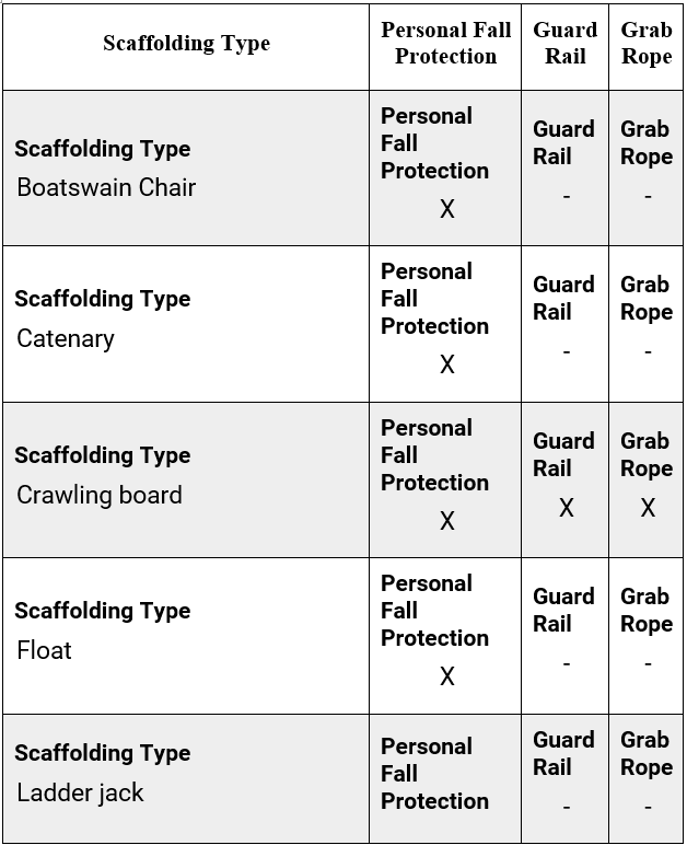
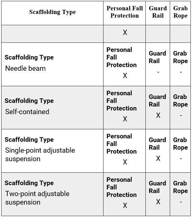
Table 1 details the types of fall protection needed with specific types of scaffolding.

Table 1

Employers are responsible for providing fall protection and ensuring its use. Since September. 2, 1997, employers have been required to have a competent person determine whether fall protection is necessary and feasible for employees erecting or dismantling supported scaffolds. Supported scaffolds consist of one or more platforms supported by rigid, load-bearing members, such as poles, legs, frames, outriggers, etc. Competent person means one who is capable of identifying existing and predictable hazards in the surroundings or working conditions which are unsanitary, hazardous, or dangerous to employees, and who has authorization to take prompt corrective measures to eliminate them.

Safe Distances from Energized Power Lines

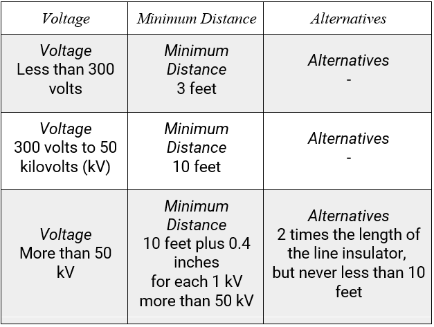
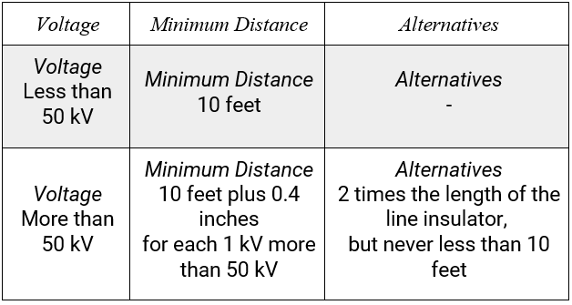
Per 29 CFR 1926.451(f)(6), scaffolds cannot be erected, used, dismantled, altered or moved closer than the distances stated below in Table 2 when near energized power lines.

Table 2 Insulated Lines

Uninsulated Lines

However, scaffolds can be moved closer if it is necessary for the performance of work, provided the power lines are de-energized or protective coverings are installed to help prevent accidental contact. For more information, refer to 29 CFR 1926.451(f)(6) Exception.

Commonly Asked Questions

Q: What types of equipment are recommended for a personal fall protection system?

A: A personal fall protection system consists of an anchorage point, body belt or body harness and might include a lanyard, deceleration device, lifeline or a combination of these.

Q: Are extension cords considered exposed power lines?

A: No. Extension cords and power tool cords are not included in the definition of an exposed power line.


Sources

29 CFR 1926 Subpart L

29 CFR 1910.27 Scaffolds and Rope Decent Systems

OSHA Safety and Health Topics – Scaffolding

OSHA Scaffolding eTool

29 CFR 1926 Subpart L

Scaffolding Hazards and Possible Solutions

ANSI/ASSP A10.8-2011

29 CFR 1926.451 Scaffolds – General Requirements


The information contained in this article is intended for general information purposes only and is based on information available as of the initial date of publication. No representation is made that the information or references are complete or remain current. This article is not a substitute for review of current applicable government regulations, industry standards, or other standards specific to your business and/or activities and should not be construed as legal advice or opinion. Readers with specific questions should refer to the applicable standards or consult with an attorney.

Source: Grainger Know How – https://www.grainger.com/know-how


Gas Cylinder Storage and Handling – Quick Tips

Hundreds of different materials are packaged in compressed gas cylinders—atmospheric gases, fuel gases, refrigerant gases, poison gases, etc. The hazards associated with these gases include oxygen displacement, explosion hazards, toxic effects and the physical hazards of a ruptured cylinder. The Occupational Safety and Health Administration (OSHA) references general requirements for compressed gases in 29 Code of Federal Regulations (CFR) 1910.101 and specific gas requirements are found in:

  • 29 CFR 1910.102 – Acetylene
  • 29 CFR 1910.103 – Hydrogen
  • 29 CFR 1910.104 – Oxygen
  • 29 CFR 1910.105 – Nitrous Oxide
  • 29 CFR 1910.110 – Storage and Handling of Liquefied Petroleum Gases (LPG)
  • 29 CFR 1910.111 – Storage and Handling of Anhydrous Ammonia

Gas Cylinder Inspection: General Requirements

29 CFR 1910.101(a) states employers must visually inspect compressed gas cylinders to ensure that they are in a “safe condition.” Visual cylinder inspections should look for leaks, bulging, defective valves, evidence of physical abuse, fire or heat damage, pitting, rusting or corrosion. If cylinders do not pass a visual inspection they need to be repaired and re-qualified per Department of Transportation (DOT) regulations.

Visual and other inspections must be conducted as described in the DOT Hazardous Materials Regulations (49 CFR 171 – 180).

Where the DOT regulations are not applicable, visual and other inspections must be conducted as prescribed in the Compressed Gas Association’s (CGA) C-6 Standard for Visual Inspection of Steel Compressed Gas Cylinders (revised June 28, 2013) and C-8 Standard for Requalification of DOT-3HT, CTC-3HT and TC-3HTM Seamless Steel Cylinders (revised November 6, 2017) pamphlets.

Gas Cylinder Storage and Handling: General Requirements

Per 29 CFR 1910.101(b), the in-plant handling, storage and utilization of all compressed gas cylinders must be in accordance with CGA Pamphlet P-1 Standard for Safe Handling of Compressed Gases in Containers (revised March 23, 2015).

Gas cylinders should be properly secured at all times to prevent tipping, falling or rolling. They can be secured with straps or chains connected to a wall bracket or other fixed surface, or by use of a cylinder stand.

The gas cylinders should be stored in a cool, dry, well-ventilated, fire-resistant area that meets all applicable federal, state and local regulations.

When a gas cylinder is empty or not being used, ensure that the valve is closed, the regulator removed and the valve protector cap is secured in place.

Gas cylinders should be transported using hand trucks designed for that purpose and the cylinders should be secured so that they do not tip, fall or roll.

Appropriate lifting devices, such as cradles or nets, are required when a crane, hoist or derrick is used to transport gas cylinders. Do not use magnets or slings to lift gas cylinders. Do not use the valve protection cap for lifting a gas cylinder.

It is necessary to take precautions so that gas cylinders are not dropped or allowed to strike each other or other objects. Dropping or striking may damage the gas cylinder valve, which could turn the gas cylinder into a dangerous torpedo with the potential to destroy property and/or injure personnel.

Consult the appropriate safety data sheet (SDS) for detailed information on the chemical contained in the gas cylinder. Specific chemical handling and storage precautions will be outlined in the SDS. The SDS will also have specifications for appropriate personal protective equipment (PPE) for worker protection.

Always reference the OSHA specific requirements highlighted earlier if handling or storing Acetylene, Hydrogen, Oxygen, Nitrous Oxide, LPG, or Anhydrous Ammonia in your facility.

Commonly Asked Questions

Q: Can full and empty cylinders be stored together?

A: According to CGA P-1 pamphlet, full and empty cylinders should be stored separately to minimize handling of cylinders.

Q: Can gasoline and other flammable liquids be stored with compressed gas cylinders?

A: No. Highly flammable substances should not be stored near gas cylinders according to the CGA’s p-1 pamphlet.

Sources:
OSHA 29 CFR 1910.101 Compressed gases (general requirements)
C-6 Standard for Visual Inspection of Steel Compressed Gas Cylinders, Edition 11, June 28, 2013
C-8 Standard for Requalification of DOT-3HT, CTC-3HT and TC-3HTM Seamless Steel Cylinders, Edition 8, November 6, 2017
P-1 Standard for Safe Handling of Compressed Gases in Containers, Edition 12, March 23, 2015
49 CFR Subtitle B Chapter I


The information contained in this article is intended for general information purposes only and is based on information available as of the initial date of publication. No representation is made that the information or references are complete or remain current. This article is not a substitute for review of current applicable government regulations, industry standards, or other standards specific to your business and/or activities and should not be construed as legal advice or opinion. Readers with specific questions should refer to the applicable standards or consult with an attorney.

Source: Grainger Know How – https://www.grainger.com/know-how


Workplace Housekeeping in General Industry – Quick Tips

Housekeeping is a broad term that refers to the routine maintenance and upkeep of a workplace. The Occupational Safety and Health Administration (OSHA) has found good workplace housekeeping reduces injuries and accidents, improves morale, reduces fire potential and can even make operations more efficient.

OSHA makes reference to housekeeping in several general industry standards:

New Walking and Working Surfaces (WWS) Standard

On November 17, 2016, OSHA published a revised WWS rule in the Federal Register with an effective date of January 17, 2017. The rule updates the general industry WWS standard specific to slip, trip and fall hazards – common issues in unkempt workplaces.

29 CFR 1910.22

The revised general industry workplace housekeeping requirements are referenced in 29 CFR 1910.22. Employers must ensure that:

  • 22(a)(1): All places of employment, passageways, storerooms, service rooms, and walking working surfaces are kept in a clean, orderly, and sanitary condition.
  • 22(a)(2):. The floor of each workroom is maintained in a clean and, to the extent feasible, in a dry condition. When wet processes are used, drainage must be maintained and, to the extent feasible, dry standing places, such as false floors, platforms, and mats must be provided.
  • 22(a)(3): Walking-working surfaces are maintained free of hazards such as sharp or protruding objects, loose boards, corrosion, leaks, spills, snow, and ice.
  • 22(d)(1): Walking-working surfaces are inspected regularly and as necessary, and maintained in a safe condition.
  • 22(d)(2): Hazardous conditions on walking-working surfaces are corrected or repaired before an employee uses the walking-working surface again. If the correction or repair cannot be made immediately, the hazard must be guarded to prevent employees from using the walking-working surface until the hazard is corrected or repaired.

Maintaining A Housekeeping Program

In order to ensure that proper workplace housekeeping is maintained, a continuous process involving both workers and custodial personnel is required. Housekeeping should be incorporated into all processes, operations and tasks performed in the workplace. Efforts should be concentrated in high traffic areas, such as around stairs, platforms and ladders; around work stations and machines; and in storage areas. Each worker needs to understand that workplace housekeeping is an integral part of his/her job and not merely a supplement to work he/she already performs. And, as workplace housekeeping becomes a standard part of operations, less time and effort are needed to maintain it at an appropriate level.

Use walk-through surveys to identify, evaluate and control the hazards that may be created by the lack of proper workplace housekeeping. These surveys send a message to all employees that workplace housekeeping is viewed as an important part of everyone’s job. A survey checklist is an effective tool to track performance and to communicate successes and areas requiring additional attention.

Frequently Asked Questions

Q: Who is responsible for workplace housekeeping?

A: All employees share the responsibilities of keeping their work stations and work areas free from the accumulation of materials. Additional responsibilities are often assigned to custodial employees or specific departmental employees.

Q: When should workplace housekeeping efforts be performed?

A: Workplace housekeeping levels are most easily maintained if they are completed throughout the day as needed. At the end of the shift, all areas should be thoroughly cleaned in preparation for the next day or the following shift.

Q: Is a written program required?

A: No. OSHA does not require a written housekeeping program for general industry. However, there is a reference to written housekeeping procedures that may be applicable under the fire prevention plan standard 29 CFR 1910.39(b) and 1910.39(c)(2):

29 CFR 1910.39(b)”Written and oral fire prevention plans. A fire prevention plan must be in writing, be kept in the workplace, and be made available to employees for review. However, an employer with 10 or fewer employees may communicate the plan orally to employees.” In accordance with 1910.39(c)(2) a fire prevention plan must include “procedures to control accumulations of flammable and combustible waste materials.”

Source

29 CFR Subpart D Walking and Working Surfaces, Revised November 2016.
29 CFR 1910, OSHA General Industry Standards


The information contained in this article is intended for general information purposes only and is based on information available as of the initial date of publication. No representation is made that the information or references are complete or remain current. This article is not a substitute for review of current applicable government regulations, industry standards, or other standards specific to your business and/or activities and should not be construed as legal advice or opinion. Readers with specific questions should refer to the applicable standards or consult with an attorney.

Source: Grainger Know How – https://www.grainger.com/know-how


Quick Course – The Basics of Forklift Safety

Course Description

This quick course covers hazards of working with forklifts – both as drivers and pedestrians and how to protect yourself from these dangers whether you are operating the forklift or working around it.


Quick Course – Report it or Regret it

Course Description

This quick course covers the importance of reporting incidents like close calls or broken/damaged equipment. It also covers tips on fixing or reporting hazards and your obligation to report.


Quick Course – Gloves Must Match Chemical Hazard

Course Description

This course covers the dangers gloves are designed to safeguard you from and the importance of matching the right glove to the hazard of work.


Quick Course – Teamwork and Culture

Course Description

This quick course covers the importance of teamwork and culture in the workplace including the dangers of not working as a team and the benefits of teamwork.


OSHA Requirements Machine Guarding – Quick Tips

Identify all the potential hazards in your workplace that require machine safeguarding and ensure they adhere to OSHA regulations.

Moving machine parts create workplace hazards and potential machinery-related injuries, making machine guards vitally important. All machines consist of three fundamental areas – the point of operation, the power transmission device and the operating controls. Machine safeguarding helps protect workers from preventable injuries in all three areas.

The Occupational Safety and Health Administration’s (OSHA’s) requirements for machine guarding are found in 29 Code of Federal Regulations (CFR) 1910 Subpart O, Machinery and Machine Guarding as detailed below;

  • 211 — Definitions
  • 212 — General requirements for all machines
  • 213 — Woodworking machinery
  • 214 — Cooperage machinery [Reserved]
  • 215 — Abrasive wheel machinery
  • 216 — Mills and calendars in the rubber/plastics industries
  • 217 — Mechanical power presses
  • 218 — Forging machines
  • 219 — Mechanical power-transmission apparatus

General Requirements

29 CFR 1910.212(a)(1) states that one or more methods of machine guarding must be used to protect operators and other employees from hazards, including those created by point of operation, in-running nip points, rotating parts, flying chips and sparks.

Hazardous Mechanical Motions and Actions

Identifying hazards is the first step toward protecting workers and promoting safety in the workplace. The basic types of hazardous mechanical motions and actions are:

Examples of Hazardous Mechanical Motions

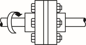
A rotating motion can be dangerous. Even smooth, slowly rotating shafts can grip clothing, and through mere skin contact, force an arm or hand into a dangerous position.

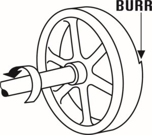
Collars, couplings, cams, clutches, flywheels, shaft ends, spindles and horizontal or vertical shafting are examples of common hazardous rotating mechanisms. The danger increases when bolts, nicks, abrasions and projecting keys or setscrews are exposed on rotating parts.
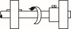
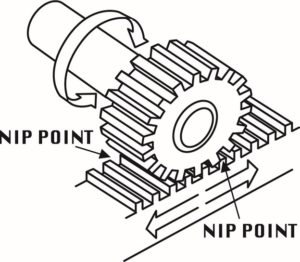
Rotating parts cause hazards such as in-running nip points. There are three main types of in-running nip points. Parts can rotate closely to each other in opposite directions while their axes are parallel to each other. When they run closely, the stock fed between two rolls produces a nip point. This danger is common on machines with intermeshing gears, rolling mills and calendars.

Rotating and tangentially moving parts also cause nip points. Potential hazards include the points of contact between a power transmission belt and its pulley, a chain and its sprocket, or a rack and pinion.
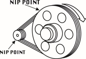
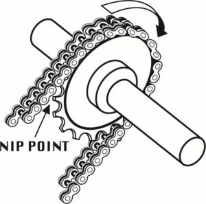
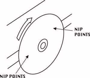
Nip points also occur between rotating and fixed parts, spoked hand wheels on flywheels, screw conveyors and the periphery of an abrasive wheel – and create shearing, crushing or abrading actions.

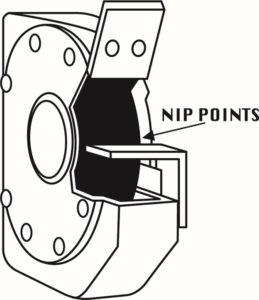
Reciprocating motions cause a back-and-forth or up-and-down action that can strike a worker or catch a worker between a moving and a stationary part.
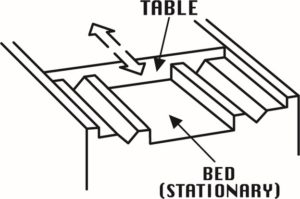
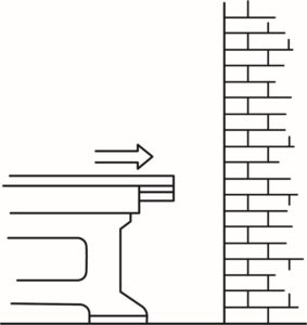
With transverse motion – movement in a straight continuous line – moving parts can catch or strike a worker in a pinch point or shear point.
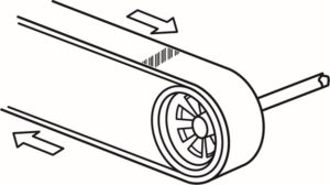
Examples of Hazardous Mechanical Actions

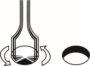
Cutting action hazards involve rotating, reciprocating or transverse motion, where finger, head and arm injuries can occur and where flying chips and scrap material can strike a worker’s eyes or face. Cutting actions are dangers with bandsaws, circular saws, and boring or drilling machines.
Punching action results when power is applied to a slide (ram) for the purpose of blanking, drawing or stamping metal or other materials. The danger occurs where stock is inserted, held and withdrawn by hand as with power presses.
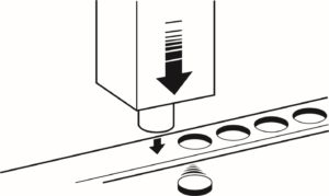
Shearing action involves applying power to a shear or knife to trim or shear materials such as metal. The danger is where stock is inserted, held and withdrawn, as with hydraulically or pneumatically powered shears.

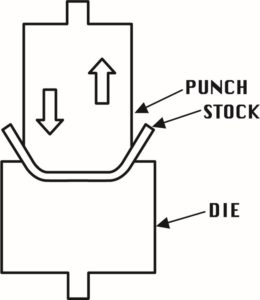
Bending action results when power is applied to a slide to draw or stamp metal or other material. This is a threat where stock is inserted, held and withdrawn, as with equipment such as power presses.
Requirements for Safeguards

Machine safeguards must meet these minimum general requirements:

  1. Prevent contact: The safeguard must prevent hands, arms or any other part of a worker’s body from contacting dangerous moving parts.
  2. Be secure: Workers should not be able to easily remove or tamper with the safeguard. Guards and safety devices should be made of durable materials that will withstand normal use. They must be firmly secured to the machine where possible or secured elsewhere if attachment to the machine is not possible.
  3. Protect from falling objects: The safeguard should ensure that no objects can fall into moving parts.
  4. Create no new hazards: A safeguard defeats its own purpose if it creates a hazard such as a shear point, a jagged edge or an unfinished surface. Edges of safeguards should be rolled or bolted so that they eliminate sharp edges.
  5. Create no interference: Any safeguard that impedes a worker from performing a job quickly and comfortably might be bypassed or disregarded. Proper safeguarding can enhance efficiency because it relieves a worker’s injury apprehensions.
  6. Allow safe lubrication: If possible, the machine should be able to be lubricated without removing the safeguard. Locating oil reservoirs outside the guard, with a line leading to the lubrication point, will reduce the need for the operator or maintenance worker to enter the hazardous area.

Types of Safeguarding

The type of operation, the size or shape of stock, the method of handling, the physical layout of the work area, the type of material and production requirements or limitations help determine the best method for safeguarding.

Safeguards are classified as either guards or devices.

Guards

Guards are barriers which prevent access to dangerous areas. There are four general types of guards:

  1. Fixed guards are permanent parts of a machine. These guards are preferable because they’re simple and permanent.
  2. Interlocked guards automatically shut off or disengage power through a tripping mechanism when it is opened or removed. The machine cannot cycle or start until the guard is replaced.
  3. Adjustable guards are useful because they accommodate various sizes of stock.
  4. Self-adjusting guards allow the opening of these barriers to be determined by the movement of the stock. As the operator moves the stock into the danger area, the guard is pushed away, providing an opening that only is large enough for the stock.

Devices

Safety devices perform several functions. They may stop a machine if any part of a body is inadvertently placed in the danger area. They may restrain or withdraw an operator’s hands from the danger area. They may require both hands on a control, therefore keeping both hands out of the danger area. They may also provide a synchronized barrier with the machines operating cycle to prevent entry into the danger area.

Devices include:

  • Presence-sensing devices are divided into two groups. Photoelectrical devices use light sources and controls that can interrupt the machine’s operating cycle. Radiofrequency or capacitance devices use a radio beam that is part of the machine control circuit. When the capacitance field is broken, the machine will stop or not activate.
  • Electromechanical sensing devices have a probe or contact bar that descends to a predetermined distance when the operator initiates the machine cycle. If there is an obstruction preventing it from descending to its full, predetermined distance, the control circuit does not start the machine cycle.
  • Pullback devices use cables attached to the operator’s hands, wrists and/or arms. They are used primarily on machines with stroking-action hazards. When the slide/ram is up (between cycles), the operator has access to the points of operation. When the slide/ram begins to descend, a mechanical link automatically assures that the operator’s hands move away from the point of operation.
  • Restraint (hold-back) devices allow the operator’s hands to travel only in a predetermined safe area and prevent the operator from reaching into a danger area. Cables or straps are attached to the operator’s hands and a fixed point. No extending or retracting actions are involved.
  • Safety trip controls, such as pressure-sensitive body bars, safety tripods and safety tripwire cables, quickly deactivate a machine in an emergency.
  • Two-hand controls require both hands and constant pressure on the controls for the machine to operate.
  • Two-hand trip requires in sync application of both the operator’s control buttons to activate the machine cycle after which the hands are free. To be effective, both the controls and trips must be located so that the operator cannot use two hands or one hand and another part of their body to trip the machine.
  • Gates are movable barriers that protect the operator at the point of operation before the machine cycle starts. To be effective, gates must be interlocked so that the machine will not begin a cycle unless the gate guard is in place.

Though not actual guards or devices, location and distance can keep employees safe by placing a machine in an infrequently traveled area or where it’s dangerous moving parts are not accessible. A thorough hazard analysis of each machine and situation is essential before using this safeguarding technique

Guard Construction

Guards designed and installed by the machine producer are desirable because they conform to the design and function of the machine, and they can be designed to strengthen the machine or to serve some additional functional purpose.

User-built guards are sometimes necessary and have some advantages. Often, with older machines, they are the only practical solution. They also might be the only choice for mechanical power transmission apparatuses in older plants, where machinery may not be powered by individual motor dries. User-built guards can be designed and built to fit unique and changing situations and can be installed on individual dies and feeding mechanisms. They also permit options for point-of-operation safeguards. When workers design and install machine guards, they develop a better knowledge of those guards and how they work.

However, there are some disadvantages. User-built guards might not conform well to the configuration and function of the machine and might be poorly designed or built.

Guard Materials

Metal, plastic, wood or any other material that is substantial enough to withstand impact and prolonged use are all used as construction materials for machine guards. In many circumstances, metal is the best material for guards. It might also be feasible to use plastic where higher machine visibility is required. Guards made of wood are generally not recommended because of their flammability and lack of durability and strength.

29 CFR 1910.219 Mechanical power-transmission apparatus, states that wood guards can be options in woodworking and chemicals industries, and in industries where vapors or gases or other conditions could deteriorate metal guards. Wood guards also may be used in construction work and in outdoor locations where extreme cold make metal guards undesirable. In all other industries, wood guards are not allowed, per 29 CFR 1910.219 (o)(2).

Summary

The list of possible machinery-related injuries created by moving machine parts is long – amputations, lacerations, crushing injuries, and abrasions, Machine safeguards are essential for protecting worker from these preventable injuries. Please click the link to review Grainger’s product line of machine guards.

Sources
29 CFR 1910 Subpart O
OSHA Machine Guarding E-Tool

Frequently Asked Questions

Q: What is the point of operation?

A: The point of operation is where work is performed on the material, such as cutting, shaping, boring, or forming of stock.

Q: When must the blades of a fan be guarded?

A: The blades of a fan must be guarded when the periphery of the blades is less than seven feet above the floor or working level. The guards must not have openings larger than one-half inch (29 CFR 1910.212(a)(5)).


The information contained in this article is intended for general information purposes only and is based on information available as of the initial date of publication. No representation is made that the information or references are complete or remain current. This article is not a substitute for review of current applicable government regulations, industry standards, or other standards specific to your business and/or activities and should not be construed as legal advice or opinion. Readers with specific questions should refer to the applicable standards or consult with an attorney.

Source: Grainger Know How – https://www.grainger.com/know-how


When Does the Lockout Tagout Standard Apply – Quick Tips

OSHA’s Control of Hazardous Energy (Lockout/Tagout) general industry standard covers the servicing and maintenance of machines and equipment in which the unexpected energization or startup of machines or equipment, or release of stored energy, could cause injury to employees. Employees servicing or maintaining machines or equipment may be exposed to serious physical harm or death if hazardous energy is not properly controlled. The Lockout/Tagout (LO/TO) standard establishes minimum performance requirements for the control of hazardous energy sources such as electrical, mechanical, hydraulic, pneumatic, chemical, and thermal.

29 CFR 1910.147(a)(1)(ii)(A-E) of the general industry standard identifies the following areas the standard does not cover:

  • Employment covered by Construction (1926), Agriculture (1928), Longshoring (1918), Marine Terminals (1917), or Shipyards (1915)
  • Installations under the exclusive control of electric utilities for the purpose of power generation, transmission and distribution, including related equipment for communication or metering
  • Exposure to electrical hazards from work on, near, or with conductors or equipment in electric-utilization installations, which is covered by 29 CFR 1910 Subpart S
  • Oil and gas well drilling and servicing

To better understand when the LO/TO standard applies, OSHA has identified two key workplace activities. The first is normal production. This is defined as any utilization of a machine or piece of equipment to perform its intended purpose. The second is servicing and/or maintenance. This is defined as any action that is necessary to prepare or maintain a machine or piece of equipment for normal production.

As a general principle, the LO/TO standard does not apply to normal production activities unless the employee is required to remove or bypass machine guarding required by 29 CFR Part 1910 Subpart O, Machinery and Machine Guarding, or place any part of their body in an area where unexpected startup of the machine or equipment may cause injury.

If any of the following exceptions or exemptions are applicable to the servicing/maintenance activity being performed, then the LO/TO standard does not apply:

  1. Complying with the minor servicing exception (29 CFR 1910.147(a)(2)(ii)(B))
  2. Utilizing the cord and plug connected equipment or hot tap exemptions (29 CFR 1910.147(2)(iii)(A) and (B) respectively)
  3. Effectively guarding the machine/equipment in compliance with 29 CFR Part 1910 Subpart O

If you’re unsure about any activity that may or may not fall under the scope of this standard, always play it safe and perform the lockout.

Commonly Asked Questions

  1. What specific criteria must be met for the minor servicing exception to apply?

A: Minor tool changes and adjustments, and other minor servicing activities that take place during normal production operations, are not covered by the standard if they are routine, repetitive, and integral to the use of the equipment for production, provided that the work is performed using alternative measures (remote oilers, specially designed servicing tools, etc.) that provide effective protection.

  1. Do I have to lock out/tag out a machine that only requires the unit to be unplugged?

A: No. The standard does not apply in situations where work on cord- and plug-connected electric equipment is under the exclusive control of the employee performing the servicing or maintenance.

  1. Are there any other standards related to lockout/tagout?

A: Yes. OSHA has used 29 CFR 1910.212, General Requirements for All Machines, and 29 CFR 1910.219, Mechanical Power Transmission Apparatus, to cite businesses for a lack of compliance. In addition, 29 CFR 1910.333, Selection and Use of Work Practices, sets forth requirements to help protect employees working on electric circuits and equipment. This section requires workers to use safe work practices, including lockout/tagout procedures. These areas also allow OSHA to issue a double citation for noncompliance.


Sources

29 CFR 1910.147, 1910.219, and 1910.333.

ANSI/ASSP Z244.1-2016, Control of Hazardous Energy Lockout/Tagout and Alternative Methods, 2016

OSHA LO/TO eTool, Lockout/Tagout Interactive Training Program, March 2008

(Rev 1/2019)


The information contained in this article is intended for general information purposes only and is based on information available as of the initial date of publication. No representation is made that the information or references are complete or remain current. This article is not a substitute for review of current applicable government regulations, industry standards, or other standards specific to your business and/or activities and should not be construed as legal advice or opinion. Readers with specific questions should refer to the applicable standards or consult with an attorney.

Source: Grainger Know How – https://www.grainger.com/know-how


Using Insulated Hand Tools to Avoid Arc Flash Incidents – Quick Tips

Insulated hand tools play a role in creating a safe workplace for employees who are working near energized circuits

Whether they’re high in the sky working on power lines, elbow-deep in a generator, or re-wiring a critical piece of control equipment on the factory floor, electrical workers need tools that are designed and engineered for maximum safety.

Because insulated tools and energized environments go hand-in-hand, there are some key points to keep in mind when buying, using and retesting such tools. Here’s a look at some of the most important:

Buying and Using Insulated Hand Tools

Used to protect workers working live or close to live parts against arc flash, arc blasts and electrocution, insulated tools are rated at 1,000 volts AC (and 1,500 volts DC), but are subjected to 10,000 volts during the product testing process (as mandated by ASTM F1505). Hand tools covered by ASTM F1505 include screwdrivers, wrenches, pliers, nippers, strippers, cable cutting tools, cable scissors, knives and tweezers.

Complying both with the National Fire Protection (NFPA) 70E® and the International Electrotechnical Commission (IEC) 60900 standards, insulated tool sets are individually tested and certified by the manufacturer for specific working conditions.

When purchasing insulated hand tools, safety directors should seek out those that comply with IEC, ASTM, and/or the Deutsches Institut fur Normung (DIN) standards. While these groups do not test the individual tools for compliance (manufacturers do their own testing), they do set the insulation performance requirements for the tools.

The Verband der Elektrotechnik, Elektronik und Informationstechnik (VDE), the association of German electro technicians, is an independent agency that tests a sample of each tool to ensure compliance.

To increase tool life and ensure that the insulated hand tools provide protection for users, be sure to:

  • Keep tools clean and dry
  • Inspect insulation before each use
  • If you doubt the integrity of the insulation, destroy the tool or have it retested
  • Follow the manufacturer’s temperature recommendations for use
  • Have a qualified person inspect and recertify tools annually for safe use
  • Use other personal protective equipment as necessary

Retesting Hand Tools

Although there aren’t specific requirements for retesting insulated hand tools, in compliance with 29 CFR 1910.335(a)(1)(ii), protective equipment must be maintained in a safe, reliable condition. Most manufacturers suggest inspecting the insulation before each use and having a qualified person perform an annual inspection and certification. To aid in the inspection process, some manufacturers offer two-layer insulation that will change color when the insulation has been breached.

When using insulated tools, make sure workers always follow the manufacturer’s recommendation. Although insulated hand tools are tested and certified to 1,000 volts AC, the testing agencies do not recommend using them on energized circuits, for example, and most insulating tools are designed only for protection from accidental contact with energized circuits


The information contained in this article is intended for general information purposes only and is based on information available as of the initial date of publication. No representation is made that the information or references are complete or remain current. This article is not a substitute for review of current applicable government regulations, industry standards, or other standards specific to your business and/or activities and should not be construed as legal advice or opinion. Readers with specific questions should refer to the applicable standards or consult with an attorney.


Source: Grainger Know How – https://www.grainger.com/know-how


Ventilation Guidelines for Flammable and Chemical Storage Cabinets – Quick Tips

Chemical storage cabinets, whether used for flammables, corrosives or pesticides/poisons,  come with capped bung openings that allow for ventilation. While cabinet manufacturers may provide the bungs for ventilation purposes, venting flammable liquid storage cabinets is NOT required or even recommended by any federal regulatory agency. Cabinet manufacturers include venting bungs for users who may be required to vent by state or local codes, individual company policies, insurance carrier policies or any other authority having jurisdiction (AHJ).

Don’t Vent Unless You Have To

According to the National Fire Protection Association (NFPA) Code 30, Flammable and Combustible Liquids Code, venting a flammable storage cabinet is not necessary for fire protection purposes. Flammable and combustible liquid storage cabinets are designed to help protect the internal contents from a fire outside of the cabinet. A vented cabinet could compromise the ability of the cabinet to protect its contents from a fire.

NFPA 30-2018 Edition, 9.5.4 states, “Storage cabinets shall not be required by this code to be ventilated for fire protection purposes.” Additionally, in Annex A, NFPA offers further reinforcement that venting is not necessary. A.9.5.4 states, “Venting storage cabinets has not been demonstrated to be necessary for fire protection purposes. Additionally, venting a cabinet could compromise the ability of the cabinet to adequately protect its contents from involvement in a fire because cabinets are not generally tested with venting. Therefore, venting of a storage cabinet is not recommended.”

If venting is being considered, 9.5.4.2 addresses some minimal design requirements. It states, “If a storage cabinet is ventilated for any reason, the vent openings shall be ducted directly to a safe location outdoors or to a treatment device designed to control volatile organic compounds (VOCs) and ignitable vapors in such a manner that will not compromise the specified performance of the cabinet and in a manner that is acceptable to the AHJ.” If the cabinet is not vented, the NFPA code requires that the bung caps remain sealed as 9.5.4.1 states, “If a storage cabinet is not ventilated, the vent openings shall be sealed with the bungs supplied with the cabinet or with bungs specified by the manufacturer.”

While not federally mandated, state or local AHJ may require venting. NFPA 30 acknowledges this under A.9.5.4 where it states, “However, it is recognized that some jurisdictions might require storage cabinets to be vented and that venting can also be desirable for other reasons, such as health and safety.”

How Do I Know If I Need to Vent My Flammable Storage Cabinet and How Is It Done?

As it’s clearly indicated above, from a federal regulatory compliance perspective there is no requirement to vent a cabinet. To determine if additional regulations or requirements apply to your specific situation, you’ll need to confer with your AHJ.

Should you learn from your AHJ that ventilating your flammable storage cabinet is a requirement, be sure to obtain clear and detailed instructions as to how the cabinet needs to be vented. They should not only supply the “how” but also specific requirements for the equipment needed to mechanically vent the cabinet.

NFPA 30 does offer additional venting guidance should the AJH deem it necessary.  A.9.5.4.2  states “A “safe location” should be selected as the location of a vent discharge to minimize the potential for ignitable vapors to travel to a source of ignition after discharge from the vent. Electrical equipment that does not meet the requirements for hazardous locations can serve as an ignition source. The Technical Committee advises that vent discharge locations should consider such factors as the following:

  1. Characteristics of the exhausted material (vapor density, toxicity, velocity of discharge, etc.)
  2. Proximity to potential ignition sources
  3. Building openings such as doors, windows, air intakes and so forth
  4. Dispersion characteristics (distance to discharge within the flammable range, direction of discharge, atmospheric conditions, and the influence of building and neighborhood buildings on discharge vapors)
  5. Likelihood of vapor accumulation following discharge, such as an accumulation under building eaves
  6. Likelihood of sufficient discharge volume to allow an ignitable concentration to reach an ignition source

Historically, NFPA 30 has provided prescriptive guidance, often based on area classification requirements, and results have been acceptable. Closer distances should be accepted only if an analysis by a qualified person justifies closer distances. Similarly, the specified distances might not be acceptable for all installations, thus the guidance provided above.

Again, these are general guidelines taken from current NFPA references. Your AHJ that’s requiring you to vent is the ultimate authority regarding how the cabinet must be vented.

The above NFPA guidelines refer specifically to flammable liquid storage cabinets; if, at the request of your AHJ, you’re required to vent a corrosives/acid cabinet, make sure to incorporate a blower that’s compatible with the vapors being exhausted. Also be aware that if it’s a hazardous material you’re venting, you may not be allowed to exhaust to the outside due to the health hazards the vapors present.

For more information on chemical storage in the workplace, see Quick Tips #181: Chemical Compatibility Concerns in Storage. For additional information on flammable liquids in the workplace, see Quick Tips #179: Flammable Liquids and Quick Tips #180: NFPA 30: A Guide to Flammable Liquids.

Commonly Asked Questions

Q: Are there any options short of venting to control the levels of vapors inside flammable and chemical storage cabinets?

A: Vapor trap filters are available for storage cabinets that contain activated carbon to aid in lowering the levels of VOCs or corrosive vapors inside the cabinets.

Q: Do I need self-closing doors?

A: Self-closing doors are not a federal requirement; however, some states and/or local municipalities do enforce the International Fire Code (IFC) or the NFPA 1 Fire Code which does mandate self-closing doors. To find out if you are in an area that requires self-closing doors, contact your local fire marshal or AHJ.

Sources
NFPA 30 Flammable and Combustible Liquids Code, 2018 Edition
29 CFR 1910.106 Flammable Liquids


The information contained in this article is intended for general information purposes only and is based on information available as of the initial date of publication. No representation is made that the information or references are complete or remain current. This article is not a substitute for review of current applicable government regulations, industry standards, or other standards specific to your business and/or activities and should not be construed as legal advice or opinion. Readers with specific questions should refer to the applicable standards or consult with an attorney.

Source: Grainger Know How – https://www.grainger.com/know-how


Ground Fault Circuit Interrupters – Quick Tips

OSHA 1910.399 defines a ground fault circuit interrupter, or GFCI, as “a device whose function is to interrupt the electric circuit to load when a fault current to ground exceeds some predetermined value, that is less than that required to operate the over-current protective device of the supply circuit.”

Ground fault circuit interrupter is designed to shut off electric power within as little as 1 /40 of a second. The mechanism compares the amount of current going into the electric equipment to the amount of current returning along the circuit conductors. If the current exceeds six milliamperes, the ground fault circuit interrupter discontinues the current to prevent electrocution.

These safety devices can be incorporated into special outlets, included as part of a power cord or placed in-line to continually monitor the current passing through a receptacle. When a difference in current is sensed, indicating a leakage, the GFCI quickly breaks the circuit to prevent injury.

Ground fault circuit interrupters protect people the way breakers and fuses protect wiring in a home or business. As electricity follows the path (route) of least resistance, if an individual were to touch an electrical system with a leak that did not have a ground fault circuit interrupter, the individual would serve as a better route for the electricity to pass through. Conversely, if the electrical system with a leak had a ground fault circuit interrupter, the device would activate before the electricity reached the person.

Where are they used?

Ideal areas for using ground fault circuit interrupters include wet or humid environments and high-risk areas where people could come into contact with ground, or ground equipment. In home use, ground fault circuit interrupters can typically be found in kitchens and bathrooms. Other applications include outdoor outlets, spas and swimming areas. Occupations that use ground fault circuit interrupters include dairy farms, breweries, steam plants and construction sites.

The following ground fault circuit interrupter regulations come from OSHA’s Construction Standard 1926.404 – Wiring Design and Protection for Construction Sub part K of the 29 Code of Federal Regulations (CFR):

1926.404 (b)(l)(ii)

Ground fault circuit interrupters (GFCIs). All 120V, single-phase 15A and 20A receptacle outlets on construction sites, which are not a part of the permanent wiring of the building or structure and which are in use by employees, shall have approved ground fault circuit interrupters for personal protection. Receptacles on a two-wire, single-phase portable or vehicle mounted generator, rated not more than 5KW, where the circuit conductors of the generator are insulated from the generator frame and all other ground surfaces need not be protected with ground fault circuit interrupters.

1926.404 (b)(l)(iii)

Assured equipment grounding conductor program. The employer shall establish and implement an assured equipment grounding conductor program on construction sites covering all cord sets, receptacles which are not a part of the building or structure and equipment connected by cord and plug which are available for use or used by employees. The program shall comply with the following minimum requirements:

1926.404 (b)(l)(iii)(A): A written description of the program, including the specific procedures adopted by the employer, shall be available at the job site for inspection and copying by the Assistant Secretary and any affected employee.

1926.404 (b)(l)(iii)(B): The employer shall designate one or more competent persons (as designed in 1926.32(f)) to implement the program.

1926.404 (b)(l)(iii)(C): Each cord set, attachment cap, plug and receptacle of cord sets, and any equipment connected by cord and plug, except cord sets and receptacles which are fixed and not exposed to damage, shall be visually inspected before each day’s use for external defects such as: deformed or missing pins, insulation damage, or indications of possible internal damage. Equipment found damaged or defective shall not be used until repaired.

Ground fault circuit program requirements

Employers must provide:

  • Written description of program
  • Competent person to implement the program
  • Inspection and testing
  • Records of test results

Inspections/Tests

Visual inspection of the following equipment is required:

  • Cord sets
  • Cap, plug and receptacle of cord sets
  • Equipment connected by cord and plug

Exceptions:

  • Receptacles and cord sets that are fixed and not exposed to damage

Frequency of tests:

  • Before first use
  • After repair and before placing back in service
  • Before use after suspected damage
  • Every three months—however, cord sets and receptacles exposed to damage must be tested at regular intervals not to exceed six months

Conduct tests for:

  • Continuity of equipment of grounding conductor
  • Proper terminal connection of equipment grounding conductor

Note: For additional information please see 29 CFR 1926.404

Q: Do I need to test GFCIs?

A: Yes, GFCIs should be tested periodically to ensure they are working properly. It is recommended to follow manufacturer’s instructions regarding the testing of the ground fault circuit interrupter.

Source

29 CFR 1926.404

29 CFR 1910.399

N.E.C. National Electric Code

OSHA booklet: Controlling Electrical Hazards


The information contained in this article is intended for general information purposes only and is based on information available as of the initial date of publication. No representation is made that the information or references are complete or remain current. This article is not a substitute for review of current applicable government regulations, industry standards, or other standards specific to your business and/or activities and should not be construed as legal advice or opinion. Readers with specific questions should refer to the applicable standards or consult with an attorney.

Source: Grainger Know How – https://www.grainger.com/know-how


Quick Course – Sexual Harassment: What Are Your Responsibilities

This quick course covers the important role supervisors play when it comes to the issue of sexual harassment in the workplace. It covers supervisor responsibilities and steps to take if approached with a complaint and employee responsibilities when it comes to sexual harassment responsibilities.


Hitching – Drawbar Connection Meeting Kit

The two most common tractor-hitching methods use the drawbar or the 3-point hitch assembly. In either case, there can be multiple elements involved in the process including connecting the implement using a hitch pin, adjusting a jack stand, attaching safety chains, connecting the PTO shaft, connecting hydraulic couplings, or plugging in electrical connections

DRIVING TIPS FOR DRIVER, TOW VEHICLE AND TRAILER 

Towing involves the interaction of a number of components: the driver, tow vehicle and trailer. Each of these contributes to the towing experience and safety of the combination. The driver is responsible for selecting the right tow vehicle and trailer for the load, hitching the unit, loading, steering, speed, and braking. All components of the tow vehicle and trailer affect towing. Safe and proper driving is a critical piece of trailer safety. Drivers should be focused and limit or eradicate distractions.

Hitching IQ

No matter which type of hitch system used, the hitch needs to have a strength rating equal to or greater than the GVWR of your trailer. Your trailer’s maximum capacity is never greater than the lowest rated part in the trailer/towing system. You also want to ensure your hitch system is in good working condition and matches the type of tongue on the trailer.

FIRST LINE OF DEFENSE: SAFETY CHAINS

Safety chains are your first line of defense if the trailer detaches.

  • Crisscross the chains to form an X beneath the trailer tongue so that it would catch the tongue should the trailer disconnect from the tow vehicle. Only enough slack to allow turning should exist.
  • If possible, the chains should be looped back to hook onto themselves
  • Do not hang an S hook on the opening of the receiver hitch, it might bounce off while driving, but loop it through the opening and connect it to the chain.

HITCHING OVERVIEW 

  • Try to do hitching and unhitching on level ground. If there is a risk of rolling, block wheels before unhitching.
  • Hitch trailed equipment only to the tractor drawbar. Hitching elsewhere may displace the centre of gravity on the tractor and can cause a backward overturn.
  • Connect each farm wagon or piece of equipment to the towing vehicle by two separate means of attachment. Most commonly this will be a draw pin and chains. It may also include a ball-hitch or three-point hitch. Use safety hitch pins (draw pins with cotter pins or other locking system) in every application.
  • Use properly rated safety chains with pins and balls of the proper size. The strength of a safety chain must be equal to the gross weight of the load being towed. Be sure no loose chains are dangling either from the drawbar or the implement.
  • Use locking pins on hydraulics.
  • Shut off the engine and wait for all moving parts to stop before un/hitching implements or when making adjustments or performing maintenance.
  • Make sure all shields and guards are in good condition and properly installed.

HAULING OVERVIEW 

  • When towing equipment without brakes, keep speeds under 40 km/hr.
  • Stopping distance increases with speed and with increased weight of towed loads. Reduce speed when hauling a load.
  • Make sure the tractor is properly counterweighted.
  • Before hauling, ensure your load is well secured. Avoid sudden starts / stops and excessive speed, especially when operating on a hillside or rough ground as it may cause your load to fall.
  • Check clearance before operating under overhead electric lines or before entering a building.
  • Always travel with the front-end loader or bucket in the lowest position possible.
  • Avoid operating attachments during road travel and keep the PTO disengaged unless absolutely necessary.
  • Transport winged and folding implements in their narrowest configuration.

FINAL WORD

Hitching and Hauling are common almost everyday occurrences on farms. Most of the time, they proceed without a “hitch”. The hitching process is fraught with dangers and risk if safety procedures are not followed with precision. 


Hitching – Drawbar Connection Meeting Kit – Spanish

QUÉ ESTÁ EN RIESGO

Los dos métodos más comunes de enganche del tractor utilizan la barra de tiro o el conjunto de enganche de 3 puntos. En cualquiera de los dos casos, puede haber múltiples elementos implicados en el proceso, como la conexión del implemento mediante un pasador de enganche, el ajuste de un caballete, la colocación de cadenas de seguridad, la conexión del eje de la TDF, la conexión de acoplamientos hidráulicos o la conexión eléctrica

CUÁL ES EL PELIGRO

CONSEJOS DE CONDUCCIÓN PARA EL CONDUCTOR, EL VEHÍCULO TRACTOR Y EL REMOLQUE 

El remolque implica la interacción de varios componentes: el conductor, el vehículo tractor y el remolque. Cada uno de ellos contribuye a la experiencia de remolque y a la seguridad de la combinación. El conductor es responsable de seleccionar el vehículo remolcador y el remolque adecuados para la carga, el enganche de la unidad, la carga, la dirección, la velocidad y el frenado. Todos los componentes del vehículo tractor y del remolque afectan al remolque. La conducción segura y adecuada es una pieza fundamental para la seguridad del remolque. Los conductores deben estar concentrados y limitar o erradicar las distracciones.

Inteligencia en el enganche

No importa el tipo de sistema de enganche que se utilice, el enganche debe tener una resistencia igual o superior al MMA de su remolque. La capacidad máxima de su remolque nunca es mayor que la parte más baja del sistema de remolque/tracción. También debe asegurarse de que su sistema de enganche esté en buenas condiciones de funcionamiento y que se ajuste al tipo de lengüeta del remolque.

COMO PROTEGERSE

PRIMERA LÍNEA DE DEFENSA: CADENAS DE SEGURIDAD

Las cadenas de seguridad son su primera línea de defensa si el remolque se desprende.

  • Entrecruce las cadenas para formar una X debajo de la lengüeta del remolque, de modo que atrape la lengüeta en caso de que el remolque se desconecte del vehículo tractor. Sólo debe haber suficiente holgura para permitir el giro.
  • Si es posible, las cadenas deben ser enrolladas para que se enganchen a sí mismas.
  • No cuelgue un gancho en forma de S en la abertura del enganche receptor, ya que podría rebotar durante la conducción, sino que hágalo pasar por la abertura y conéctelo a la cadena.

RESUMEN DEL ENGANCHE 

  • Intente realizar el enganche y desenganche en un terreno llano. Si hay riesgo de que ruede, bloquee las ruedas antes de desenganchar.
  • Enganche el equipo arrastrado sólo a la barra de tiro del tractor. Enganchar en otro lugar puede desplazar el centro de gravedad del tractor y provocar un vuelco hacia atrás.
  • Conecte cada vagón o equipo agrícola al vehículo tractor por dos medios de enganche distintos. Lo más habitual es que se trate de un pasador de tracción y cadenas. También puede incluir un enganche de bola o de tres puntos. Utilice pasadores de enganche de seguridad (pasadores de tracción con chavetas u otro sistema de bloqueo) en todas las aplicaciones.
  • Utilice cadenas de seguridad con pasadores y bolas del tamaño adecuado. La resistencia de la cadena de seguridad debe ser igual al peso bruto de la carga remolcada. Asegúrese de que no hay cadenas sueltas que cuelguen de la barra de tiro o del implemento.
  • Utilice pasadores de bloqueo en el sistema hidráulico.
  • Apague el motor y espere a que se detengan todas las piezas móviles antes de desenganchar los implementos o cuando se ajusten o realicen tareas de mantenimiento.
  • Asegúrese de que todos los escudos y protecciones están en buen estado y correctamente instalados.

RESUMEN DE TRANSPORTE 

  • Cuando remolque equipos sin frenos, mantenga la velocidad por debajo de los 40 km/h.
  • La distancia de parada aumenta con la velocidad y con el aumento del peso de la carga remolcada. Reduzca la velocidad cuando arrastre una carga.
  • Asegúrese de que el tractor está correctamente contrapesado.
  • Antes de transportar, asegúrese de que la carga está bien sujeta. Evite los arranques y paradas bruscos y la velocidad excesiva, especialmente cuando trabaje en una ladera o en un terreno accidentado, ya que puede provocar la caída de la carga.
  • Compruebe el espacio libre antes de operar bajo líneas eléctricas aéreas o antes de entrar en un edificio.
  • Viaje siempre con el cargador frontal o la cuchara en la posición más baja posible.
  • Evite utilizar los implementos durante los desplazamientos por carretera y mantenga la TDF desconectada a menos que sea necesario.
  • Transporte los implementos con alas y plegables en su configuración más estrecha.

CONCLUSIÓN

El enganche y el transporte son actividades casi cotidianas en las granjas. La mayoría de las veces, se llevan a cabo sin problemas. El proceso de enganche está plagado de peligros y riesgos si no se siguen con precisión los procedimientos de seguridad.


Working in extreme heat Meeting Kit – Spanish

QUÉ ESTÁ EN RIESGO

EL ÍNDICE DE CALOR 

Para las personas que trabajan al aire libre cuando hace calor, tanto la temperatura del aire como la humedad afectan a la sensación de calor. El “índice de calor” es un valor único que tiene en cuenta tanto la temperatura como la humedad. Cuanto más alto es el índice de calor, más calor se siente, ya que el sudor no se evapora fácilmente y enfría la piel. El índice de calor es una medida mejor que la temperatura del aire por sí sola para estimar el riesgo que suponen las fuentes de calor ambiental para los trabajadores.

TRABAJO AL AIRE LIBRE

Los trabajadores que se incorporan a trabajos al aire libre suelen ser los que más riesgo corren de sufrir enfermedades relacionadas con el calor. En la mayoría de los casos, el trabajador implicado estaba en su primer día de trabajo y en el 80% de los casos el trabajador implicado sólo había estado en el trabajo durante cuatro o menos días. Por eso es importante aumentar gradualmente la carga de trabajo o permitir descansos más frecuentes para ayudar a los nuevos trabajadores y a los que se reincorporan a un puesto de trabajo después de un tiempo de ausencia a crear una tolerancia a las condiciones de calor. 

CUÁL ES EL PELIGRO

FACTORES QUE PROVOCAN EL ESTRÉS TÉRMICO 

  • trabajar bajo la luz directa del sol en los meses de verano.
  • La humedad en el lugar de trabajo (más del 50% de humedad relativa).
  • Trabajar en determinados lugares de trabajo, como fundiciones, plantas químicas, panaderías y cocinas comerciales.
  • trabajar en minas, especialmente en minas profundas con gradientes geotérmicos.

COMO PROTEGERSE

Los trabajadores expuestos al calor extremo o que trabajan en entornos calurosos pueden correr el riesgo de padecer estrés térmico. La exposición al calor extremo puede provocar enfermedades y lesiones laborales. El estrés térmico puede provocar un golpe de calor, un agotamiento por calor, calambres por calor o sarpullidos por calor. El calor también puede aumentar el riesgo de lesiones en los trabajadores, ya que puede dar lugar a palmas sudorosas, gafas de seguridad empañadas y mareos. También pueden producirse quemaduras por el contacto accidental con superficies calientes o con el vapor.

GESTIONAR EL ESTRÉS/LA ENFERMEDAD POR CALOR EN EL TRABAJO 

  1. Diseñe el lugar de trabajo para reducir el estrés térmico
  • utilice máquinas (por ejemplo, polipastos y mesas elevadoras) para reducir las exigencias físicas del trabajo.
  • controlar el calor en su origen utilizando barreras aislantes y reflectantes (por ejemplo, aislar las paredes de los hornos).
  • extraer el aire caliente y el vapor producido por las operaciones.
  • utilizar acondicionadores de aire para reducir la temperatura y la humedad.
  • utilizar ventiladores si la temperatura es inferior a 35°C (si se utilizan ventiladores cuando la temperatura es superior a 35°C pueden recircular el aire caliente, lo que puede impedir la refrigeración).
  • Proporcionar:
  • zonas de trabajo frescas y con sombra
  • zonas de descanso con aire acondicionado
  1. Plan para reducir el estrés por calor
  • Evaluar las exigencias de todos los trabajos y establecer un plan para los días y lugares de trabajo calurosos.
  • aumentar la frecuencia y la duración de las pausas de descanso.
  • programar los trabajos extenuantes a horas más frescas del día, como por ejemplo a primera hora de la mañana, a última hora de la tarde o por la noche.
  • Proporcionar agua potable fresca cerca de los trabajadores.
  • recordar a los trabajadores que deben beber un vaso de agua al menos cada 15 ó 20 minutos para mantenerse hidratados.
  • Advierta a los trabajadores que deben evitar la luz solar directa.
  • asignar más trabajadores o reducir el ritmo de trabajo.
  • asegúrese de que los trabajadores tengan tiempo para aclimatarse a una intensidad de trabajo modificada.
  • capacitar a los trabajadores para que reconozcan los signos y síntomas del estrés térmico.
  • poner en marcha un “sistema de compañeros”, ya que es probable que los trabajadores no se den cuenta de sus propios síntomas.
  • investigue cualquier incidente relacionado con el calor del que informen los trabajadores.
  • asegúrese de que haya trabajadores formados en primeros auxilios en el lugar de trabajo
  • cree un plan de respuesta de emergencia para responder a las enfermedades relacionadas con el calor.
  • aconsejar a las trabajadoras embarazadas o con problemas de salud que consulten a su médico sobre el trabajo en el calor y hacer las adaptaciones oportunas.
  1. Adaptarse a entornos calurosos

Para los trabajadores sin experiencia en condiciones de calor, hay dos maneras de ayudarles a tolerar el calor:

  1. aumentar gradualmente el nivel de actividad durante una o dos semanas
  2. aumentar gradualmente la cantidad de tiempo que se pasa en condiciones de trabajo calurosas

Para los trabajadores con experiencia en condiciones de calor, pero que pueden haber estado enfermos o ausentes del trabajo durante 9 o más días, el trabajador deberá readaptarse gradualmente al calor.

  1. Los trabajadores deben llevar ropa de protección adecuada
  • llevar ropa de verano ligera y transpirable (si procede)
  • cubrir la cabeza para evitar la exposición a la luz solar directa.
  • Llevar ropa reflectante en situaciones de mucho calor radiante.
  • considere la posibilidad de utilizar ropa aislante refrigerada por aire, agua o hielo en entornos muy calurosos.
  • evitar la ropa que no sea transpirable, como la ropa de protección química. Si los trabajadores deben llevarla, deben prestar mucha atención a los síntomas que sugieren que pueden estar enfermos debido al calor

CONCLUSIÓN

Una temperatura corporal humana saludable es de 37°C. Una variación de la temperatura corporal superior a 1°C puede ser un indicio de enfermedad o de condiciones ambientales que superan la capacidad del cuerpo para afrontarlas. Trabajar a temperaturas muy altas puede ser peligroso para la salud, ya que puede provocar un golpe de calor, un agotamiento por calor o un desmayo.


Working in extreme heat Meeting Kit

THE HEAT INDEX 

For people working outdoors in hot weather, both air temperature and humidity affect how hot they feel. The “heat index” is a single value that takes both temperature and humidity into account. The higher the heat index, the hotter the weather feels, since sweat does not readily evaporate and cool the skin. The heat index is a better measure than air temperature alone for estimating the risk to workers from environmental heat sources.

OUTDOOR WORK

Workers new to outdoor jobs are generally most at risk for heat-related illnesses. In most cases, the worker involved was on their first day of work and in 80% of the cases the worker involved had only been on the job for four or fewer days. That’s why it’s important to gradually increase the workload or allow more frequent breaks to help new workers and those returning to a job after time away to build up a tolerance for hot conditions. 

FACTORS THAT CAUSE HEAT STRESS 

  • working in direct sunlight in the summer months.
  • humidity in the workplace (more than 50% relative humidity).
  • working in certain workplaces such as foundries, smelters, chemical plants, bakeries and commercial kitchens.
  • working in mines, especially deep mines with geothermal gradients.

Workers who are exposed to extreme heat or work in hot environments may be at risk of heat stress. Exposure to extreme heat can result in occupational illnesses and injuries. Heat stress can result in heat stroke, heat exhaustion, heat cramps, or heat rashes. Heat can also increase the risk of injuries in workers as it may result in sweaty palms, fogged-up safety glasses, and dizziness. Burns may also occur as a result of accidental contact with hot surfaces or steam.

MANAGE HEAT STRESS/ILLNESS AT WORK 

  1. Design The Workplace to Reduce Heat Stress
  • use machines (for example, hoists and lift-tables) to reduce the physical demands of work.
  • control the heat at its source by using insulating and reflective barriers (for example, insulate furnace walls).
  • exhaust hot air and steam produced by operations.
  • use air conditioners to reduce the temperature and humidity.
  • use fans if the temperature is below 35°C (if fans are used when the temperature is above 35°C they may recirculate the hot air, which can prevent cooling).
  • provide:
  • cool, shaded work areas
  • air-conditioned rest areas
  1. Plan Ahead to Reduce Heat Stress
  • assess the demands of all jobs and put a plan in place for hot days and workplaces.
  • increase the frequency and length of rest breaks.
  • schedule strenuous jobs to cooler times of the day such as in the early morning, late afternoon or night.
  • provide cool drinking water near workers.
  • remind workers to drink a cup of water at least every 15 to 20 minutes to stay hydrated.
  • caution workers to avoid direct sunlight.
  • assign more workers or slow down the pace of work.
  • make sure workers have time to acclimatize to a modified intensity of work.
  • train workers to recognize the signs and symptoms of heat stress.
  • start a “buddy system” because people are not likely to notice their own symptoms.
  • investigate any heat-related incidents reported by workers.
  • make sure workers trained in First Aid are available and on-site
  • create an emergency response plan to respond to heat-related illnesses.
  • advise workers who are pregnant or have a medical condition to consult their physician about working in the heat and make appropriate accommodations.
  1.  Adjust to Hot Environments

For workers with no experience in hot conditions, there are two ways to help them tolerate the heat:

  1. gradually increase the activity level over one to two weeks
  2. gradually increase the amount of time spent in hot working conditions

For workers with experience in hot conditions, but who may have been ill or away from work for 9 or more days, the worker will need to gradually readjust to the heat.

  1. Workers Must Wear Suitable Clothing
  • wear light and breathable summer clothing (if applicable).
  • cover the head to prevent exposure to direct sunlight.
  • wear reflective clothing in a high radiant-heat situation.
  • consider air, water or ice-cooled insulated clothing for very hot environments.
  • avoid clothing that isn’t breathable, such as chemical protective clothing. If the workers must wear it, they should pay close attention to symptoms that suggest they may be ill due to heat

FINAL WORD

A healthy human body temperature is 37°C. A change of body temperature exceeding 1°C can be an indication of illness or environmental conditions beyond the body’s ability to cope. Working in very hot temperatures can be dangerous to your health, causing heat stroke, heat exhaustion or fainting.


Hitching – Drawbar Connection Stats and Facts

FACTS

  1. The two most common tractor-hitching methods use the drawbar or the 3-point hitch assembly. In either case, there can be multiple elements involved in the process including connecting the implement using a hitch pin, adjusting a jack stand, attaching safety chains, connecting the PTO shaft, connecting hydraulic couplings, or plugging in electrical connections.
  2. If drivers hitch their trailers properly and drive safely, then accidents involving hitched trailers are unlikely. An improperly hitched trailer is more likely to become detached from the towing vehicle. After a trailer becomes detached from its towing vehicle, it becomes an uncontrolled “missile on the highway.”
  3. There are common injuries that occur during hitching like pinch points, crush points, blunt trauma, and run over.
  4. Farmers and others who use tractors are at risk for severe injury or death if proper hitching methods are not used when towing or pulling objects with tractors.
  • In a recent article, NIOSH warned that improperly attaching a tow chain to a point above the tractor’s drawbar can cause tractors to suddenly flip backward. These rear rollovers often result in injury or death.

STATS

  • 27 incidents of sudden rear rollover of tractors were documented in New York by NIOSH’s Occupational Health Nurses in Agricultural Communities program. Sixteen of these incidents resulted in death. Improperly hitching equipment or material for towing caused the rollovers in 60% of these incidents. Environmental circumstances such as muddy conditions, wet ground, snow-covered, hilly or uneven terrain may have contributed to some of the incidents.
  • In 16 (59%) of the 27 reported incidents, improper hitching of equipment or material for towing was believed to be the primary cause of the rollover; 10 (63%) of these 16 rollovers resulted in fatalities. The remaining 11 rollovers were associated with various factors, including ensnaring the towed item on a stump, imbalance resulting from pulling an excessively heavy load, or ascending a steep incline in forward gear rather than backing up the hill; five of these incidents resulted in fatalities.
  • In each of the 16 rear rollovers attributed to improper hitching, attachment of the tow chain to a point above the drawbar was the principal cause of the rollover. Six incidents occurred while the operators were pulling logs, four while removing stumps, and six while pulling vehicles or implements. Only one of these 16 tractors had been equipped with a ROPS; the operator of this tractor had not been wearing a safety belt and had sustained fractures of the clavicle and humerus after being thrown from the tractor.
  • Of the 16 injured persons, 13 were male. One was aged 13 years; three, 20-40 years; seven, 40-60 years; and five, greater than 70 years. All 10 persons with fatal injuries had sustained massive chest and/or head injuries; in comparison, five (83%) of the six persons with nonfatal injuries had sustained pelvic and/or limb injuries.  


Hitching – Drawbar Connection Stats and Facts – Spanish

HECHOS

  1. Los dos métodos más comunes de enganche del tractor utilizan la barra de tiro o el conjunto de enganche de 3 puntos. En cualquiera de los dos casos, puede haber múltiples elementos implicados en el proceso, incluyendo la conexión del implemento mediante un pasador de enganche, el ajuste de un caballete, la colocación de cadenas de seguridad, la conexión del eje de la toma de fuerza, la conexión de acoplamientos hidráulicos o el enchufe de las conexiones eléctricas.
  2. Si los conductores enganchan sus remolques correctamente y conducen con seguridad, los accidentes con remolques enganchados son poco probables. Un remolque mal enganchado tiene más probabilidades de desprenderse del vehículo tractor. Cuando un remolque se desprende de su vehículo tractor, se convierte en un “misil en la carretera” incontrolado.
  3. Hay lesiones comunes que se producen durante el enganche como puntos de pellizco, puntos de aplastamiento, traumatismos por golpes y atropellos.
  4. Los agricultores y otras personas que utilizan tractores corren el riesgo de sufrir lesiones graves o de morir si no se utilizan métodos de enganche adecuados al remolcar o arrastrar objetos con los tractores.
  • En un artículo reciente, el NIOSH advertía de que el enganche incorrecto de una cadena de remolque a un punto situado por encima de la barra de tracción del tractor puede hacer que los tractores vuelquen repentinamente hacia atrás. Estos vuelcos hacia atrás suelen provocar lesiones o la muerte.

ESTADÍSTICAS

  • El programa de enfermeras de salud laboral en comunidades agrícolas del NIOSH documentó 27 incidentes de vuelco repentino de tractores en Nueva York. Dieciséis de estos incidentes tuvieron como resultado la muerte. El enganche incorrecto del equipo o del material de remolque causó los vuelcos en el 60% de estos incidentes. Las circunstancias ambientales, como condiciones de barro, suelo húmedo, terreno nevado, montañoso o irregular, pueden haber contribuido a algunos de los incidentes.
  • En 16 (59%) de los 27 incidentes notificados, se cree que la causa principal del vuelco fue el enganche incorrecto del equipo o del material de remolque; 10 (63%) de estos 16 vuelcos provocaron víctimas mortales. Los 11 vuelcos restantes se asociaron a diversos factores, como el enganche del elemento remolcado en un tocón, el desequilibrio resultante de remolcar una carga excesivamente pesada, o el ascenso de una pendiente pronunciada en marcha adelante en lugar de retroceder por la colina; cinco de estos incidentes se saldaron con víctimas mortales.
  • En cada uno de los 16 vuelcos traseros atribuidos a un enganche incorrecto, el enganche de la cadena de remolque a un punto por encima de la barra de tiro fue la causa principal del vuelco. Seis incidentes se produjeron mientras los operadores tiraban de troncos, cuatro mientras retiraban tocones y seis mientras tiraban de vehículos o implementos. Sólo uno de estos 16 tractores estaba equipado con una ROPS; el operador de este tractor no llevaba puesto el cinturón de seguridad y sufrió fracturas de clavícula y húmero tras salir despedido del tractor.
  • De los 16 heridos, 13 eran hombres. Uno tenía 13 años; tres, entre 20 y 40 años; siete, entre 40 y 60 años; y cinco, más de 70 años. Las 10 personas con lesiones mortales habían sufrido lesiones masivas en el tórax y/o la cabeza; en comparación, cinco (83%) de las seis personas con lesiones no mortales habían sufrido lesiones en la pelvis y/o las extremidades.  


Work Refusals – COVID-19

Course Description

This course covers your responsibilities when it comes to refusing work due to COVID-19 infection. It covers legal obligations and other information including information on encounters between the employee and employer and other personal circumstances that may be involved in the refusal.


Cryogenic Safety – Quick Tips

What Does Cryogenic Mean?

The term “cryogenic” means producing or related to low temperatures. Cryogenic liquids are liquefied gases created by cooling a liquid to a low temperature under high pressure, which creates special health and safety hazards. These liquids have boiling points below –238° F (–150° C) and are gases at normal room temperatures and pressures. Different cryogens become liquids under different conditions of temperature and pressure, but all have two common properties: they are extremely cold and small amounts of the liquid can expand into very large volumes of gas. Dry ice is a super-cooled solid (carbon dioxide) that sublimes directly into gaseous carbon dioxide at –109.3° F. Sublimation is the transition of a substance directly from the solid to the gas state, without passing through the liquid state.

Dry ice, most cryogenic liquids and the gasses they produce can be placed into one of three groups:

  • Inert gases– These gases do not react chemically to any great extent and do not burn or support combustion. Examples of this group are nitrogen, helium, neon, argon, dry ice (carbon dioxide) and krypton.
  • Flammable gases– Some cryogenic liquids produce a gas that can burn in air. The most common examples are hydrogen, methane and liquefied petroleum gas (LPG).
  • Oxygen– Many materials considered as non-combustible can burn in the presence of liquid oxygen. Organic materials can react explosively with liquid oxygen.

Cryogenics and dry ice have many uses and often play a role in industrial and medical applications. Other applications include fast freezing of some foods and the preservation of some biological materials. The freezing of portions of the body to destroy unwanted or malfunctioning tissue is known as cryosurgery.

Physical Effects of Cryogenic Liquids and Dry Ice

The extreme temperatures of cryogenic liquids and dry ice cause most solid matter to become more brittle. Materials such as carbon steel, plastics and rubber should not be used in direct contact with cryogenic liquids or dry ice because they can fracture or shatter extremely easily.

Flammable gases such as hydrogen, methane and LPG can burn or explode. Hydrogen is particularly hazardous.

Liquid hydrogen and liquid helium are both so cold that they can liquefy air on contact resulting in an oxygen-enriched atmosphere.

Materials that are usually considered non-combustible, such as aluminum, carbon steel, cast iron, stainless steel and zinc may burn in the presence of liquid oxygen.

Dry ice sublimes directly to a gas which can lead to dangerous pressures when stored in closed containers or areas.

Without adequate ventilation or pressure-relief devices on cryogenic containers, enormous pressure can build up. The pressure can cause a boiling liquid expanding vapor explosion (BLEVE).

Health Hazards of Cryogenic Liquids and Dry Ice

There are three groups of health hazards associated with cryogenic liquids and dry ice – extreme cold, asphyxiation and toxicity.

Extreme cold:

Contact with cryogenic liquids and their cold gases can produce effects on the skin similar to a thermal burn, as can contact with dry ice. Brief exposures that may not affect the hands can damage delicate tissues such as the eyes. Prolonged exposure of the skin or contact with cold surfaces can cause frostbite. Tissues that have been frozen will be painless while still frozen and might look waxy yellow. Thawed frostbitten skin will be very painful, red and swollen and can become infected.

Unprotected skin can stick to materials that are cooled by cryogenic liquids and dry ice, similar to the way some children stick their tongues to flagpoles in the winter. However, where cryogenic liquids and dry ice are involved, metallic materials are not the only ones that cause this risk. It is important to remember that even nonmetallic materials are extremely dangerous to touch. Removing skin from any material can cause a tearing of the flesh.

Asphyxiation:

Prolonged breathing of extremely cold air may damage the lungs. Also, when cryogenic liquids and dry ice form a gas, the gas is very cold and some are heavier than air. These cold, heavy gases do not disperse well, tend to accumulate near the floor and displace air. When there is not enough air, asphyxiation and death can occur. This is a serious hazard especially in enclosed or confined spaces.

Toxicity:

Both cryogenic liquids and dry ice can produce very large volumes of gas at room temperatures. For example, one liter of liquid nitrogen vaporizes into 695 liters of nitrogen gas when at room temperature.

Each cryogenic liquid or dry ice can cause specific health effects. Refer to the manufacturer’s Safety Data Sheet (SDS) for information about the toxic hazards of a specific cryogen.

First Aid

Contact with dry ice, cryogenic liquids and their gases, and any cooled surfaces should be avoided. If contact does occur, immediately flush the area with large quantities of warm water (104°F). Do not rub the affected area as rubbing can cause further damage. Obtain medical attention as quickly as possible.

If oxygen loss overcomes a person working with cryogenic liquids or dry ice, move the victim to a well-ventilated area. Apply CPR if the victim’s breathing has stopped. Supply oxygen if the victim has difficulty breathing and summon emergency medical help.

Personal Protective Equipment for Cryogenic Liquids and Dry Ice Safety

Personal protective equipment (PPE) is critical to cryogenic liquid and dry ice safety. It is essential to choose the right PPE for each job. Consult each material’s SDS for specific guidance. Generally, chemical-splash goggles and face shields should always be worn during the transfer and handling process of cryogenic liquids to guard against splashes and spills. Loose-fitting, insulated cryogenic gloves should also be worn. The gloves must be loose so they can be thrown off quickly if cryogenic liquid spills into them. To protect any exposed skin, long-sleeve shirts and trousers without cuffs are suggested. Additionally, when handling cryogenic liquids, pant legs should go over the tops of footwear so spills cannot get into boots or shoes and cause extreme tissue damage before the footwear can be removed. Cryogenic liquids flow very freely and can penetrate woven or other porous clothing. Wearing a cryogenic apron is suggested to help prevent this from occurring.

If working in an area where an oxygen-deficient atmosphere could be produced due to the off-gassing of cryogenic liquids or dry ice, an air-supplying respirator must be used, such as an airline respirator with an egress bottle or a self-contained breathing apparatus (SCBA).

Cryogenic Liquid and Dry Ice-Specific Equipment

Cryogenic liquids and dry ice are shipped and used in thermally insulated containers specifically designed to withstand rapid temperature changes and extreme differences in temperature and vent gases to prevent pressure build-ups within the container.

Dewar flasks are non-pressurized, vacuum-jacketed vessels, somewhat like a thermos bottle, designed for cryogenic liquids. They have a loose-fitting cap or plug that prevents air and moisture from entering yet allows excess pressure to vent. Some dewar flasks have an outer vessel of liquid nitrogen for insulation.

Liquid cylinders are pressurized containers designed for cryogenic liquids. This type of cylinder has valves for filling and dispensing the cryogenic liquid and a pressure-control valve with a bursting disk as backup protection.


Commonly Asked Questions

Q: Why can’t I wear a cartridge-style air-purifying respirator to protect from liquid-nitrogen vapors?

A: Nitrogen itself is not a danger. In fact, normal air is 78 percent nitrogen. The danger is that liquid nitrogen vaporizes so quickly that it displaces oxygen. Oxygen comprises about 21 percent of normal air. When it falls below 18 percent, we do not have enough oxygen to function normally. Cartridge-style air-purifying respirators are only made to remove contaminants, so they are inappropriate for an environment that is oxygen deficient.

Q: What kinds of gloves are needed for working with cryogenics and dry ice?

A: Gloves should be insulated and made to withstand the low temperatures of cryogenic liquids and dry ice. They should also be loose fitting for cryogenic liquids, so they can be easily removed if a cryogenic liquid spill should go inside the glove.

Q: How cold is liquid nitrogen, and how cold is dry ice?

A: Nitrogen condenses to a liquid at –320°F. Dry ice starts subliming at –109.3°F.

Sources

Pamphlet P-12: Safe Handling of Cryogenic Liquids, Compressed Gas Association, March 2017

Cryogen Safety, National Institute of Standards and Technology (NIST)

NFPA 55: Compressed Gases and Cryogenic Fluids, National Fire Protection Association, 2020 Edition

Laboratory Safety Guideline: Dry Ice, Harvard Campus Services Environmental Health and Safety, November 2019


The information contained in this article is intended for general information purposes only and is based on information available as of the initial date of publication. No representation is made that the information or references are complete or remain current. This article is not a substitute for review of current applicable government regulations, industry standards, or other standards specific to your business and/or activities and should not be construed as legal advice or opinion. Readers with specific questions should refer to the applicable standards or consult with an attorney.

Source: Grainger Know How – https://www.grainger.com/know-how


Hitching – Drawbar Connection Fatality File

Orchard Laborer Dies after Being Struck and Run Over by Dump Trailer, Washington 

A 49-year-old orchard worker was fatally injured when he was struck and run over by a dump trailer that became unhitched from a tractor. At the time of the incident, the operator of the tractor was pulling the trailer up the side of a rough, steep dirt orchard road. The victim and another worker were loading the trailer with rocks that were excavated from the orchard rows. The victim went behind the trailer, as it was moving, to pick up rocks from the ground. The tractor started to lose traction, causing the trailer to hop. The hopping motion caused the trailer coupler to unhitch from the trailer hitch ball. The trailer rolled down the sloped road, and struck and ran over the victim. Emergency medical services were contacted and arrived on the scene. The victim was transported to the hospital where he was put on life support. Approximately two days after being admitted the victim was taken off life support and passed away. Following the incident, investigators noted that the trailer hitch ball on the tractor was not the proper size for the trailer coupler, and the safety chains and other safety equipment were not properly connected or not functioning.  


Hitching – Drawbar Connection Fatality File – Spanish

Un trabajador de un huerto muere tras ser golpeado y atropellado por un remolque basculante, Washington 

Un trabajador de un huerto, de 49 años, resultó mortalmente herido al ser golpeado y atropellado por un remolque volquete que se desenganchó de un tractor. En el momento del incidente, el operador del tractor estaba halando el remolque por el lado de un camino de tierra áspero y empinado del huerto. La víctima y otro trabajador estaban cargando el remolque con rocas excavadas en las hileras del huerto. La víctima fue detrás del remolque, mientras éste se movía, para recoger las rocas del suelo. El tractor empezó a perder tracción, haciendo que el remolque saltara. El movimiento de salto hizo que el enganche del remolque se desenganchara de la bola de enganche de este. El remolque rodó por la carretera en pendiente, golpeó y atropelló a la víctima. Se contactó con los servicios médicos de emergencia, que llegaron al lugar de los hechos. La víctima fue trasladada al hospital, donde se le aplicó la respiración artificial. Aproximadamente dos días después de su ingreso, se le retiró el soporte vital y falleció. Tras el incidente, los investigadores observaron que la bola de enganche del tractor no era del tamaño adecuado para el enganche del remolque, y que las cadenas de seguridad y otros equipos de seguridad no estaban bien conectados o no funcionaban.