Refuelling equipment Fatality File – Spanish

Un hombre muere en una explosión de un tanque de combustible 

TENSAS PARISH, La. – Según los diputados del jefe de Bomberos del Estado, han concluido su investigación sobre la causa de la explosión de un tanque de combustible que se cobró la vida de un operador de camión dispensador.

Según los diputados del SFM, el 29 de diciembre de 2020 alrededor de las 2:00 PM, el equipo de Protección contra Incendios del Distrito # 1 de Tensas respondió a un informe de una explosión fuera de Hogue Road en Newellton. Los bomberos dicen que llegaron a la escena donde un tanque de combustible había explotado, matando al operador e incendiando un camión de pasajeros, así como la maquinaria cercana.

Las autoridades dicen que la identificación oficial está pendiente de la autopsia de la Oficina del Forense de Tensas Parish, sin embargo, se cree que la víctima es un hombre de 56 años de Newellton.

Tras investigar el lugar y revisar los vídeos de vigilancia, los investigadores determinaron que la explosión se produjo mientras la víctima cargaba de combustible un tanque de la propiedad que se utilizaba para alimentar equipos de construcción. La causa oficial del incendio sigue siendo indeterminada, aunque los investigadores de la SFM no pueden descartar una ignición por electricidad estática del combustible mientras se estaba dispensando.

Las autoridades dicen que les gustaría recordar a todos los residentes de Luisiana que coloquen los contenedores de combustible en el suelo cuando los rellenen, ya que esto puede reducir el peligro potencial de la electricidad estática. Además, también quieren aconsejarles que eviten fumar o utilizar dispositivos electrónicos mientras reabastecen los vehículos y/o los contenedores.


Refuelling equipment Fatality File

Man Dies in Fuel Tank Explosion 

TENSAS PARISH, La. – According to State Fire Marshal deputies, they’ve concluded their investigation into the cause of a fuel tank explosion that claimed the life of a dispensing truck operator.

Per the SFM deputies, on December 29, 2020 around 2:00 PM, the District #1 Tensas Fire Protection team responded to a report of an explosion off of Hogue Road in Newellton. Firefighters say they arrived on scene where a fuel tank had exploded, killing the operator and setting fire to a passenger truck as well as nearby machinery.

Authorities say official identification is pending autopsy by the Tensas Parish Coroner’s Office, however, the victim is believed to be a 56-year-old man from Newellton.

After investigating the scene and reviewing surveillance video, investigators determined the explosion occurred while the victim was fueling a tank on the property which was being used to power construction equipment. The official cause of the fire currently remains undetermined, although SFM investigators are unable to rule out a static electricity ignition of the fuel as it was being dispensed.

Authorities say they would like to remind all Louisiana residents to place fuel containers on the ground when refilling them as this can reduce the potential danger of static electricity. In addition, they also would like to advise you to avoid smoking or using electronic devices while refueling vehicles and/or containers.


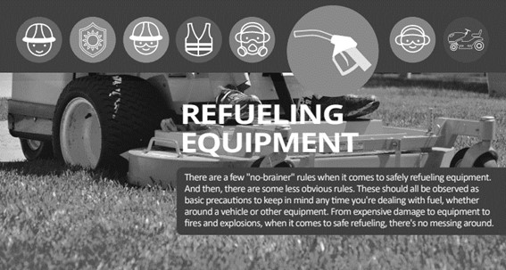
Refuelling equipment Picture This

Source: https://www.turfassistant.com


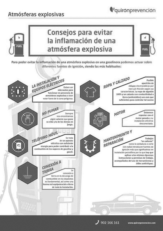
Refuelling equipment Picture This – Spanish

Fuente: https://www.quironprevencion.com/


Emergency Lighting and Exit Sign Requirements – Quick Tips

There are numerous regulatory agencies and codes that govern emergency lighting and exit sign requirements. These regulating authorities include the Occupational Safety and Health Administration (OSHA), National Fire Protection Association (NFPA), Joint Commission on Accreditation of Healthcare Organizations (JCAHO), International Building Code and International Fire Code. Above and beyond the requirements of these agencies, employers must also follow the requirements of their local authority having jurisdiction (AHJ). The local AHJ is whoever’s responsible for monitoring and enforcing local building codes and/or fire codes. Some large cities, such as New York City and Chicago, have their own unique codes and requirements for exit signs and emergency lighting. For employers unsure of who to reach out to regarding local emergency exit requirements, the local fire marshal or inspector is a good starting point.

Under 29 Code of Federal Regulation (CFR) 1910.34(c) OSHA defines “exit route” as, “a continuous and unobstructed path of exit travel from any point within a workplace to a place of safety (including refuge areas).” An exit route includes all vertical and horizontal areas along the route and consists of the following three parts:

  • Exit access−means that portion of an exit route that leads to an exit. An example of an exit access is a corridor on the fifth floor of an office building that leads to a two-hour fire resistance-rated enclosed stairway (the Exit).
  • Exit−means that portion of an exit route that is generally separated from other areas to provide a protected way of travel to the exit discharge. An example of an exit is a two-hour fire resistance-rated enclosed stairway that leads from the fifth floor of an office building to the outside of the building.
  • Exit Discharge−means the part of the exit route that leads directly outside or to a street, walkway, refuge area, public way, or open space with access to the outside. An example of an exit discharge is a door at the bottom of a two-hour fire resistance-rated enclosed stairway that discharges to a place of safety outside the building.

OSHA’s requirements for lighting and marking exit routes are covered under 1910.37(b). It states that each exit route must be adequately lighted so that an employee with normal vision can see along the exit route and each exit must be clearly visible and marked by a sign reading “Exit.” Additional requirements include the following:

  • Each exit route door must be free of decorations or signs that obscure the visibility of the exit route door.
  • If the direction of travel to the exit or exit discharge is not immediately apparent, signs must be posted along the exit access indicating the direction of travel to the nearest exit and exit discharge. Additionally, the line-of-sight to an exit sign must clearly be visible at all times.
  • Each doorway or passage along an exit access that could be mistaken for an exit must be marked “Not an Exit” or similar designation, or be identified by a sign indicating its actual use (e.g., closet).
  • Each exit sign must be illuminated to a surface value of at least five foot-candles (54 lux) by a reliable light source and be distinctive in color. Self-luminous or electroluminescent signs that have a minimum luminance surface value of at least .06-foot-lamberts are permitted.
  • Each exit sign must have the word “Exit” in plainly legible letters not less than six inches (15.2 centimeters (cm)) high, with the principal strokes of the letters in the word “Exit” not less than 3/4- inch (1.9 cm) wide.

OSHA makes reference to its acceptance of the NFPA’s emergency exit requirements under 1910.35, where it notes that employers who are following the exit-route provisions of NFPA 101, Life Safety Code, meet OSHA’s requirements. OSHA also acknowledges that those following the International Code Council’s, International Fire Code, satisfy OSHA’s compliance requirements. The latest editions of both the Life Safety Code and International Fire Code were published in 2015.

NFPA‘s Exit Sign Requirements

Additional guidance regarding exit signs is provided within the 2015 edition of NFPA 101, Life Safety Code, section 7.10. It contains details regarding the placement, visibility and acceptable forms of illumination for exit signs. Among the placement requirements it states that any new exit signs must be located so that no point in an exit access corridor is in excess of the sign’s rated viewing distance or 100-feet, whichever is less, from the nearest sign. And exit signs with directional indicators must be placed in every location where the direction of travel to reach the nearest exit is not apparent.

Regarding the visibility of exit signs, the NFPA states that every sign must be located and of such size, distinctive color, and design that it is readily visible and must contrast with the background where it’s placed. It continues by stating, “No decorations, furnishings, or equipment that impairs visibility of a sign shall be permitted. No brightly illuminated sign (for other than exit purposes), display, or object in or near the line of vision of the required exit sign that could distract attention from the exit sign shall be permitted.”

The Life Safety Code offers many details regarding acceptable illumination of exit signs. Under section 7.10.1.2 it states that all exit signs must be illuminated by a reliable light source and must be legible in both normal and emergency exit lighting modes. Section 7.10 breaks illumination into two broad categories: externally illuminated and internally illuminated. Externally illuminated refers to a source of illumination that comes from outside the exit sign while internally illuminated exit signs possess the illumination source inside the sign.

For externally illuminated signs, the Life Safety Code section 7.10.6.3 requires a level of illumination of not less than five foot-candles (54 lux) at the illuminated surface and a contrast ratio of not less than five-tenths.

Internally illuminated signs must be listed in accordance with the American National Standards Institute (ANSI)/Underwriters Laboratory (UL) 924, Standard for Emergency Lighting and Power Equipment. The Life Safety Code does allow for three exceptions to this for certain approved existing exit signs (section 7.10.7.1). The exceptions are:

  • They are approved existing signs.
  • They are existing signs having the required wording in legible letters not less than four inches (100 millimeter (mm)) high.
  • They are signs that are in accordance with Exit Door Tactile Signage (7.10.1.3) and Floor Proximity Exit Signs (7.10.1.6).

Also under internally illuminated, the Life Safety Code section 7.10.7.2 details the illumination requirements for photoluminescent signs. Photoluminescent is defined as “having the ability to store incident electromagnetic radiation typically from ambient light sources, and release it in the form of visible light.” Photoluminescent signs must be continually illuminate while the building is occupied; the charging illumination must be a reliable light source as determined by the AHJ.

Emergency Lighting Requirements

Sometimes referred to as egress lighting, emergency lighting is designed to illuminate and identify hallways, stairwells and exits to facilitate a safe and orderly evacuation from a facility. Emergency lighting is generally required in all commercial, industrial, educational, religious, institutional, public housing, medical and many other facilities whether for-profit or non-profit. And while OSHA does not have any regulations specific to emergency lighting, the NFPA’s Life Safety Code addresses the topic in detail. The local AHJ is the best resource to answer emergency lighting compliance questions related to your specific occupancy.

Within the Life Safety Code, the NFPA’s requirements for emergency lighting are referenced under section 7.9. Emergency illumination (when required) must be provided for a minimum of 1.5-hours in the event of failure of normal lighting. The emergency lighting must be arranged to provide initial illumination of not less than an average of one foot-candle (10.8-lux) and a minimum at any point of 0.1-foot-candle (1.1-lux) measured along the path of egress at floor level. These levels can decline to a minimum of 0.6-foot-candle (6.5-lux) average and 0.06-foot-candle (0.65-lux) at any one point at the end of emergency lighting time (1.5-hours). The maximum illumination at any one point can be no more than 40 times the minimum illumination at any one point to prevent excessively bright and dark spots (section 7.9.2.1.3). And the emergency lighting system must be arranged to provide illumination automatically in the event of any interruption of normal lighting (section 7.9.2.3).

Testing Requirements for Emergency Lighting

Section 7.9.3, of the Life Safety Code, addresses the NFPA’s requirements for periodic testing of emergency lights. The section acknowledges three different categories of emergency lights: traditional, self-testing/self-diagnostic and computer based self-testing/self-diagnostic. It essentially requires both a monthly activation test, where the lights remain illuminated for a minimum of 30-seconds, and an annual test where the lights are activated for 1.5-hours to simulate a long term emergency event. Written records of the monthly and annual tests must be maintained for inspection by the AHJ. Computer based emergency lighting systems must be capable of generating a self-report of testing at all times. Again, best to check with your AHJ to ensure your testing and recording keeping program is sufficient.

Definitions and Formulas

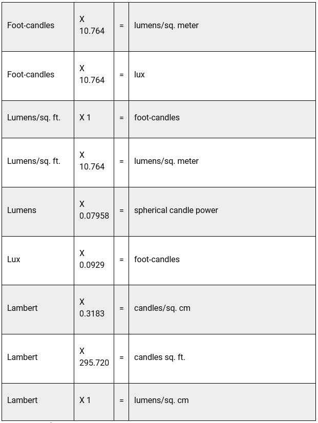
The intensity of visible light is measured in units of candles. The rate of flow of light (luminous flux) is measured in lumens. One lumen is the flux on one square foot of a sphere, one foot in radius with a light source of one candle at the center, and radiating uniformly in all directions. Both foot-candle and lux are measurements of light intensity on a surface. One foot-candle is the intensity of one candle at a distance of one foot away onto a one square foot surface. Lux is essentially the metric equivalent. It is the intensity of one candle at a distance of one meter away onto a one square meter surface. Foot lambert is the unit measure of physical brightness on any surface emitting or reflecting visible light.

Summary

Emergency lights and exit signs often do not get much attention until they are needed. To ensure a safe evacuation in an emergency:

  • Make sure that all exit paths are adequately lit,
  • Post appropriate signage,
  • Properly maintain your emergency lights and exit signs, and
  • Perform monthly and annual inspection and keep your records up to date.

Frequently Asked Questions

Q: Is there a requirement for exit sign color? Some facilities have green, other facilities have red.

A: There is no OSHA requirement for specific colors; however, OSHA states it must be distinctive in color from the background. NFPA 101 Section 7.10.1.8 states “signs must be of a distinctive color and design that is readily visible and shall contrast with decorations, interior finish and other signs.” Some states or local jurisdictions may require a certain color. Always best to check with your local AHJ.

Q: When is a “NO EXIT” sign required?

A: OSHA does not require the use of “NO EXIT”; however, guidance is provided in NFPA Life Safety Code 101 Section 7.10.8.3.1: “NO EXIT” sign is needed where “any door, passage, or stairway that is neither an exit nor a way of exit access and that is located or arranged so that it is likely to be mistaken for an exit.”

Sources

29 CFR 1910 Subpart E
NFPA 101 Life Safety Code
Fundamentals of Industrial Hygiene, 6th edition


The information contained in this article is intended for general information purposes only and is based on information available as of the initial date of publication. No representation is made that the information or references are complete or remain current. This article is not a substitute for review of current applicable government regulations, industry standards, or other standards specific to your business and/or activities and should not be construed as legal advice or opinion. Readers with specific questions should refer to the applicable standards or consult with an attorney.

Source: Grainger Know How – https://www.grainger.com/know-how


Start your Electrical Safety Program – Quick Tips

Keep workers safe by developing and implementing an electrical safe work program (ESWP) that incorporates these key elements

An extremely potent source of energy that powers lights, tools, machinery and many other devices that we use in our daily lives, electricity can also cause injury or death when not handled properly.

A national consensus safety standard that identifies safe work practices to protect workers from the hazards of electricity, including electric shock and electrocution, arc flash, and arc blast, the National Fire Protection Association’s NFPA 70: National Electric Code (NEC) for electrical design, installation and inspection safety standards addresses commercial, residential and industrial occupancies.
Getting Proactive About Safety

There are other proactive steps you can take to help prevent electrical shock or similar injuries: Keep workers away from energized equipment or circuits and train qualified workers on the correct procedures when working on energized equipment or circuits. Prior to using or performing maintenance on electrical equipment, the employee should first check that it is safe by:

  • Verifying that electrical equipment is not located in a hazardous environment, such as a damp/wet location or where it is exposed to high temperatures and flammable gases and vapors.
  • Making sure overcurrent and safety devices, such as fuses, circuit breakers, and ground fault circuit interrupters (GFCI), have not been tampered with and are working correctly.
  • Inspecting the power cord and plug to ensure there are no defects, such as cuts in the insulation exposing bare wiring.
  • Identifying whether the equipment has an emergency shutoff switch and where it is located prior to use.
  • Making sure there is sufficient space around the electrical equipment or circuit to allow for operation and maintenance.
  • Removing all personal metal jewelry prior to using or working on electrical equipment or circuits.
  • De-energizing electrical equipment before testing or repairing in accordance with the Lockout/Tagout standard 29 CFR 1910.147. (If de-energizing the electrical equipment or circuit is not feasible, then appropriate tools and personal protective equipment [PPE] must be used and worn.)

Electrical safety is the responsibility of everyone on the job site. It is important to establish an ESWP that includes employee training on electrical safety. Training employees on the basics of electrical safety should include its effects on the body, first aid procedures when someone is shocked, how to fight an electrical fire and how to identify hazards. Follow these do’s and don’ts when developing your plan of action:

Do:

  • Read and follow electrical equipment instruction manuals prior to using
  • Use safety signs, barricades and tags to identify and protect electrical equipment
  • Only use extension cords as a temporary solution
  • Use waterproof cords in an outdoor application
  • Contact a certified electrician when electrical repair is needed

Don’t:

  • Overload outlets by using splitters
  • Touch electrical equipment, including power cords with wet or damp hands
  • Allow dirt, grease or dust to accumulate on electrical equipment
  • Use temporary wiring in place of permanent wiring
  • Use cords or equipment that are not properly grounded

Sources:

Electrical Safety in the Workplace, OSHA


The information contained in this article is intended for general information purposes only and is based on information available as of the initial date of publication. No representation is made that the information or references are complete or remain current. This article is not a substitute for review of current applicable government regulations, industry standards, or other standards specific to your business and/or activities and should not be construed as legal advice or opinion. Readers with specific questions should refer to the applicable standards or consult with an attorney.

Source: Grainger Know How – https://www.grainger.com/know-how


Truck Loading Safety – Quick Tips

The rules and regulations regarding standard safe loading practices of enclosed and flatbed types of trailers for a semi-tractor service is extensively covered in truck driver training schools. Current information can also be found on the website of several different agencies involved with the trucking industry (see sources).

The following are some topics for concern:

Selection of Binding Chains: (49 CFR 393.102)

Truckers frequently use chains to tie down their loads securely, to enhance safety and abide by the law. There are two important factors to keep in mind when evaluating chains:

  1. The word “grade” describes the type of chain. For example, a “Grade 7” chain is popular with many carriers, despite its higher expense. It is a strong chain specifically for load securement, made from heat-treated carbon steel with a boron additive. “Grade 8” and “Grade 10” chains are made of alloy steel designed for heavy lifting.
  2. The “safety factor” of chains refers to a fraction of maximum load weight that the chain can carry before breaking. If a chain can hold 1,000 pounds before breaking, and has a safety factor of 4, the chain would have a working load limit of 250 pounds (250=1/4 of 1000). Truckers are required to use chains with a “working load limit” equal to 1/2 times the weight of the load (49CFR 393.102(a)(2)). In this example, using a chain that has a working load limit of 250 pounds, truckers would need one chain for every 500 pounds.

Tie Downs: Ratchet vs Lock Binders: (49 CFR 393.102)

Applicable U.S. Federal Motor Carrier Safety Regulations (FMCSR) state there must be one tie down every 10 feet for general cargo and every 8 feet for metal cargo. There must be enough tie downs so that when combined their working load limit equals half the weight of the cargo secured. At least two tie downs must be used in securing metal articles. Since there are several variables in determining how many tie downs are required for securing cargo, check out regulation 49 CFR 393.110 for more detailed information. Selection of ratchet or lock binders is not specified and left to the user’s discretion and preferences.

Current U.S. Federal Motor Carrier Safety Regulations (FMCSR) state in the 2nd paragraph of 3.7.1 that vehicles that weigh over 10,000 pounds must be loaded accordingly to the provisions in section 10 which applies to heavy vehicles, equipment and machinery.

There is no mention of saddle mounts to haul large trucks and an effort is underway by the American Trucking Association (ATA) to get this included into the FMCSR standard. A saddle mount is a truck or tractor towing other vehicles with the front axle of each towed vehicle mounted on top of the frame of the proceeding vehicle. Saddle mounting is a great way to transport more than one vehicle without the use of a trailer or multiple drivers.

Commonly Asked Questions

Q: What guideline can I use in selecting chains to secure and tie down my loads?

A: The American Trucking Association (ATA), Commercial Vehicle Safety Alliance (CVSA) and Federal Highway Administration (FHWA) all offer information to help you with cargo safety standards. Refer to the websites listed at the end of this document.

Q: Where can I get the latest news on trucking regulations and hazards?

A: The American Trucking Association (ATA).

Q: How can I avoid costly violations of safety rules?

A: By obtaining training through safety seminars such as that offered by the Commercial Vehicle Safety Alliance (CVSA).

Sources

Title 49—Transportation, 49CFR 393, Subparts A—General, and I—Protection Against Shifting Cargo
http://www.gpo.gov/fdsys/pkg/CFR-2010-title49-vol5/xml/CFR-2010-title49-vol5-part393.xml

ATA (American Trucking Association) http://www.trucking.org
For latest information on current events, news, laws, safety features, and regulatory issues.

FMCSR (US Federal Motor Carrier Safety Regulations) www.fmcsa.dot.gov
For trucking Industry news, education, outreach and issues.

CVSA (Commercial Vehicle Safety Alliance) www.cvsa.org
For topics and references on motor carriers, vehicles, cargo safety standards, compliance, education and enforcement.

FHWA (Federal Highway Administration) www.fhwa.dot.gov
For interpretations and guidance on safety and regulatory issues.

Safety Transportation Services – www.stsny.com


The information contained in this article is intended for general information purposes only and is based on information available as of the initial date of publication. No representation is made that the information or references are complete or remain current. This article is not a substitute for review of current applicable government regulations, industry standards, or other standards specific to your business and/or activities and should not be construed as legal advice or opinion. Readers with specific questions should refer to the applicable standards or consult with an attorney.

Source: Grainger Know How – https://www.grainger.com/know-how


Overhead Hoist (Underhung) Inspection – Quick Tips

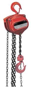
Overhead hoists commonly are found in many industries. They can be made with chain or wire rope and can be operated manually or with electric or air power. These units can be an essential part of a production line used to load raw materials or move finished goods. As vital as they can be to the production line, they are often some of the more neglected equipment in a facility, many times only getting attention after they fail or are no longer functioning. Preventive maintenance and frequent overhead hoist inspection can prevent costly downtime and potentially dangerous situations.

Overhead Hoist Regulations

Overhead hoist inspection and testing requirements, specifically for underhung overhead hoists, are not found in an OSHA standard. Some relevant information can be found in general industry standard 29 CFR 1910.179, which addresses overhead and gantry cranes. Other general requirements can be found in construction standard 1926.554. The standard that most specifically addresses the requirements of overhead hoists is an ASME/ANSI consensus standard, B30.16 for overhead hoists (underhung). This standard is part of the B30 series of standards from the American Society of Mechanical Engineers (ASME) on cableways, cranes, derricks, hoists, hooks, jacks and slings. Some of the highlights of the inspection requirements from the B30.16 standard are outlined below. The complete standard is available for purchase directly from ASME.

Definitions

Abnormal operating conditions:

Environmental conditions that are unfavorable, harmful or detrimental to the operation of a hoist, such as excessively high or low ambient temperatures, exposure to weather, corrosive fumes, dust-laden or moisture-laden atmospheres and hazardous locations.

Designated person:

A person selected or assigned by the employer or the employer’s representative as to perform specific duties.

Heavy service:

Service that involves operation within the rated load limit, which exceeds normal service.

Normal service:

Service that involves operation with randomly distributed loads within the rated load limit or uniform loads less than 65% of the rated load for not more than 15% of the time for manually operated hoists and 25% of the time for electric or air-powered hoists.

Severe service:

Service that involves normal or heavy service with abnormal operating conditions.

Overhead Hoist Inspection Requirements

A designated person should inspect hoists before their initial use and on regular intervals to verify compliance with ASME/ANSI B30.16. The specific inspection requirements are found in Table 1 and Table 2 of the B30.16 standard, which are reprinted below with written permission from ASME. The inspections are classified into frequent inspections that do not require documentation and periodic inspections that require documentation. The interval between inspections depends on the service of the hoist. The owner’s manual specific to the hoist is another good source for inspection and maintenance requirements and should be based on the requirements of this standard.

Commonly Asked Questions

Q: Does the OSHA standard 1910.179 on overhead and gantry cranes apply to overhead wire and chain hoists?

A: Not specifically. Many of the requirements are the same, but underhung hoists are specifically addressed in the consensus standard ANSI/ASME B30.16. For more information, see Quick Tips #107: Overhead Crane Safety 29 CFR 1910.179.

Q: Can OSHA cite me for not following a consensus standard?

A: Yes. Industry consensus standards might be evidence that a hazard is recognized and there is a feasible means of correcting such a hazard. If you do not follow the consensus standard, it is possible to be cited under the general duty clause.

Sources

ASME/ANSI B30.16-2003
29 CFR 1910.179
29 CFR 1926.554


The information contained in this article is intended for general information purposes only and is based on information available as of the initial date of publication. No representation is made that the information or references are complete or remain current. This article is not a substitute for review of current applicable government regulations, industry standards, or other standards specific to your business and/or activities and should not be construed as legal advice or opinion. Readers with specific questions should refer to the applicable standards or consult with an attorney.

Source: Grainger Know How – https://www.grainger.com/know-how


Types of Smoke Alarms and Detectors – Quick Tips

Smoke alarms are essential in all businesses and industrial facilities. In the event of a fire, the alarm will sound and alert all to the danger and providing an early warning. There are a number of different types of smoke alarms, so choosing the proper one for your facilities can get confusing.

NFPA provides the following guidelines for smoke alarms:

  • Choose smoke alarms that have the label of a recognized testing laboratory.
  • Smoke alarms should be installed at least 10 feet (three meters) from a cooking appliance to minimize false alarms when cooking.
  • Mount smoke alarms high on walls or ceilings (remember, smoke rises). Wall-mounted alarms should be installed not more than 12 inches away from the ceiling (to the top of the alarm).
  • If you have ceilings that are pitched, install the alarm within three feet of the peak but not within the apex of the peak (four inches down from the peak). .
  • Don’t install smoke alarms near windows, doors, or ducts where drafts might interfere with their operation.
  • Never paint smoke alarms. Paint, stickers, or other decorations could keep the alarms from working.
  • For the best protection, interconnect all smoke alarms. When one smoke alarm sounds they all sound. Interconnection can be done using hard-wiring or wireless technology.
  • When interconnected smoke alarms are installed, it is important that all of the alarms are from the same manufacturer. If the alarms are not compatible, they may not sound.

As always, make sure to follow manufacturer’s installation instructions and verify all codes and compliance with your authority having jurisdiction (AHJ). That could include your building inspector, fire marshal or insurance bureau.

Smoke Detector Types

There are currently three types of smoke alarms on the market: ionization, photoelectric and combination ionization/photoelectric.

An ionization smoke alarm contains a small amount of radioactive material. The radiation passes through an ionization chamber which is an air-filled space between two electrodes and permits a small, constant current between the electrodes. Any smoke that enters the chamber absorbs the alpha particles, which reduces the ionization and interrupts the current, setting off the alarm. This type of alarm is generally more responsive to flaming fires.

Photoelectric smoke alarms operate using a light source, a light beam collimating system and a photoelectric sensor. When smoke enters the optical chamber and crosses the path of the light beam, some light is scattered by the smoke particles, directing it at the sensor and thus activating the alarm. This type of alarm is generally more responsive to fires that begin with a long period of smoldering.

Combination smoke alarms feature both ionization and photoelectric technologies. Ionization smoke alarms respond faster to high energy fires, whereas photoelectric detectors respond better to low energy smoldering fires. The best overall protection is provided by using combination smoke alarms.

Smoke Alarm Power Sources

Smoke alarms also vary in how they are powered. Nine volt battery powered smoke alarms are very popular due to their low cost; however, care must be taken to replace the battery on a regular basis.

Smoke alarms are also available in 120 volt and long life 10 year rated lithium battery options. Many local or state building codes may require 120 volt interconnected smoke alarms with a battery back-up in case of power outages. The interconnected feature allows all smoke alarms to be linked together. This is especially important in multi-levels homes or in apartment buildings. Smoke alarms with high intensity strobe lights are also available for the hearing impaired.

Regardless of the type of alarm selected, proper placement and maintenance of the device is crucial. Follow all manufactures instructions for placement, testing and maintenance. The NFPA suggests battery replacement at least once a year on battery equipped units and a monthly test to verify the alarm function. Many users utilize daylight saving time in the spring and the fall as a reminder to change batteries.

Commonly Asked Questions

Q: How often should I change my smoke alarm?

A: The NFPA suggests changing your smoke alarms every 10 years.

Q: Are there options for the hearing impaired?

A: Yes. There are smoke alarms that use visual and audible warnings. These use a bright flashing strobe light in conjunction with the horn to warn of danger.

Q: Why is my smoke alarm chirping (or beeping)?

A: This is usually an indication that the battery is dying and needs to be replaced.

Q: Are there distance or square footage requirements for smoke alarm installation?

A: NFPA 72: National Fire Alarm and Signaling Code – 2019 Edition paragraph 29.8.1.provides installation guidelines for single and multiple-station smoke alarms. It is best to always check with the AHJ for code requirements and also the insurance carrier for the facility. 

Sources

National Fire Protection Association (NFPA): Report on Smoke Alarms in U.S. Home Fires – 2019

National Fire Protection Association (NFPA): Installing and Maintaining Smoke Alarms

National Fire Protection Association (NFPA): NFPA 72: National Fire Alarm and Signaling Code – 2019

National Fire Protection Association (NFPA): Ionization vs. Photoelectric – 2014

Related Articles


The information contained in this article is intended for general information purposes only and is based on information available as of the initial date of publication. No representation is made that the information or references are complete or remain current. This article is not a substitute for review of current applicable government regulations, industry standards, or other standards specific to your business and/or activities and should not be construed as legal advice or opinion. Readers with specific questions should refer to the applicable standards or consult with an attorney.

Source: Grainger Know How – https://www.grainger.com/know-how


Pre-Operational Inspection of Equipment Meeting Kit

THE PRE-OPERATIONAL SAFETY INSPECTION 

 “An ounce of prevention is worth a pound of cure.” Getting into the habit of regularly inspecting all equipment is a simple but important preventative measure, and should be part of every operator’s daily pre-shift routine.  

A useful tool is the Pre-Operational Inspection Checklist. Implementing the use of a paper checklist system reminds the operator to regularly perform all pre-shift checks, ensures that problems are documented and communicated to supervisors, and helps pinpoint when and how changes in the condition of the equipment occurred.

  • Performing the pre-operational check is important for the safety of the operator and everyone in its working environment. Unfortunately, this safety check is often forgotten or ignored. Not every operator is aware of the items that need to be checked before they can start their machine and begin to perform their daily tasks.
  • The equipment operator can prevent downtime, extend service life and ensure more efficient operation with just a few minutes of preventive inspection both pre- and post-operation.
  • The key is consistency. These inspections must be engrained into all parties and performed every day.

THE INSPECTION CHECKLIST

  • Check tires, rims or undercarriage for damage or abnormal wear and clear away debris. Much like you don’t operate at full capacity on a broken foot or while wearing shoes that are broken or don’t fit, a machine can be hobbled by the inefficiencies of the tires or tracks it sits on. Identify and report any damage or potential damage.
  • Check fluid levels – engine and hydraulic oil, diesel and diesel exhaust fluid (DEF), and coolant. Fluids are the lifeblood of each machine and require specified levels to operate properly. A sudden drop in fluid levels may point to any number of problems with the machine that require immediate attention (blown hoses, leaking filter, etc.).
  • Clear any accumulated debris from around the radiator and other engine components. The engine is made of moving parts and belts that generate heat and friction – and systems designed to cool the engine compartment require room to breathe. It’s important to check and remove any clutter or material from the jobsite that may have found its way into the engine compartment.
  • Check the fuel, oil, air and other filters for signs of damage or leaking. 
  • Check belts (alternator, fan, etc.). A worn and frayed belt is another wear item that is relatively easy to replace. 
  • Identify greasing points and frequency.
  • Check for leaking or pooled fluid around and under the machine. 
  • Check auxiliary hydraulic connections and pressure. 
  • Check for new signs of structural damage, scratches or dents on the machine. 
  • Check for damage on ground engaging tools (buckets, teeth, etc.). 
  • Inspect the attachment mount-up to ensure proper connection. 
  • Inspect the operator compartment and clear away any debris or obstructions. 
  • Check and set mirrors. 
  • Familiarize yourself with the control style and change as needed. 
  • Identify auxiliary/attachment controls. 
  • Start the engine and review console indicators and warnings. 
  • If equipped, check the rear-view camera. 
  • Review all external surroundings from the cab. 

FINAL WORD

A visual “circle check” or pre-operational inspection of equipment prior to every use will reduce the chance of equipment being operated in an unsafe condition. This makes it easier to spot and deal with maintenance issues early before they turn into a problem causing downtime, equipment damage or expensive repairs.


Pre-Operational Inspection of Equipment Meeting Kit – Spanish

QUÉ ESTÁ EN RIESGO

LA INSPECCIÓN DE SEGURIDAD PREOPERACIONAL 

“Una onza de prevención vale más que una libra de cura”. Adquirir el hábito de inspeccionar regularmente todos los equipos es una medida preventiva sencilla pero importante y debería formar parte de la rutina diaria de todo operario antes del turno.  

Una herramienta útil es la lista de comprobación de la inspección preoperacional. Implementar el uso de un sistema de lista de comprobación en papel recuerda al operario que debe realizar regularmente todas las comprobaciones previas al turno, garantiza que los problemas se documenten y se comuniquen a los supervisores, y ayuda a señalar cuándo y cómo se han producido los cambios en el estado del equipo.

  • Realizar la comprobación previa al trabajo es importante para la seguridad del operario y de todas las personas que se encuentran en su entorno de trabajo. Lamentablemente, esta comprobación de seguridad suele olvidarse o ignorarse. No todos los operarios son conscientes de los elementos que deben comprobarse antes de poner en marcha su máquina y comenzar a realizar sus tareas diarias.
  • El operador del equipo puede evitar el tiempo de inactividad, prolongar la vida útil y garantizar un funcionamiento más eficiente con sólo unos minutos de inspección preventiva tanto antes como después de la operación.
  • La clave es la coherencia. Estas inspecciones deben estar arraigadas en todas las partes y realizarse todos los días.

COMO PROTEGERSE

LA LISTA DE COMPROBACIÓN DE LA INSPECCIÓN

  • Compruebe si los neumáticos, las llantas o el tren de rodaje presentan daños o un desgaste anormal y elimine los residuos. Al igual que no se puede trabajar a pleno rendimiento con un pie roto o con unos zapatos rotos o que no encajan, una máquina puede verse afectada por la ineficacia de los neumáticos o las orugas sobre las que se asienta. Identifique e informe de cualquier daño o daño potencial.
  • Compruebe los niveles de fluidos: aceite del motor e hidráulico, gasóleo y líquido de escape (DEF), y refrigerante. Los fluidos son el alma de cada máquina y requieren niveles específicos para funcionar correctamente. Una caída repentina de los niveles de fluidos puede indicar cualquier problema en la máquina que requiera atención inmediata (mangueras reventadas, fugas en el filtro, etc.).
  • Limpie los residuos acumulados alrededor del radiador y otros componentes del motor. El motor está formado por piezas móviles y correas que generan calor y fricción, y los sistemas diseñados para refrigerar el compartimento del motor necesitan espacio para respirar. Es importante comprobar y eliminar cualquier desorden o material del lugar de trabajo que pueda haberse colado en el compartimento del motor.
  • Compruebe que los filtros de combustible, aceite, aire y otros no presentan daños ni fugas. 
  • Compruebe las correas (alternador, ventilador, etc.). Una correa desgastada y deshilachada es otro elemento de desgaste relativamente fácil de sustituir. 
  • Identifique los puntos de engrase y su frecuencia.
  • Compruebe que no hay fugas o charcos de líquido alrededor y debajo de la máquina. 
  • Compruebe las conexiones hidráulicas auxiliares y la presión. 
  • Compruebe si hay nuevos signos de daños estructurales, arañazos o abolladuras en la máquina. 
  • Compruebe si hay daños en las herramientas de enganche al suelo (cazos, dientes, etc.). 
  • Inspeccionar el montaje de los implementos para asegurar su correcta conexión. 
  • Inspeccione el compartimento del operador y elimine cualquier residuo u obstrucción. 
  • Compruebe y ajuste los espejos. 
  • Familiarícese con el estilo de control y cámbielo si es necesario. 
  • Identifique los controles auxiliares/de enganche. 
  • Arranque el motor y revise los indicadores y advertencias de la consola. 
  • Si está equipado, compruebe la cámara de visión trasera. 
  • Revise todo el entorno externo desde la cabina.

CONCLUSIÓN

Una “comprobación en círculo” visual o una inspección preoperacional del equipo antes de cada uso reducirá la posibilidad de que el equipo funcione en condiciones inseguras. Esto facilita la detección y el tratamiento temprano de los problemas de mantenimiento antes de que se conviertan en un problema que provoque tiempos de inactividad, daños en los equipos o reparaciones costosas.


General Hitching and Hauling Meeting Kit – Spanish

QUÉ ESTÁ EN RIESGO

ESTOS SON LOS TÉRMINOS PARA ENTENDER LOS PROCEDIMIENTOS DE ENGANCHE Y TRANSPORTE

Enganches y receptores– Se refiere al dispositivo acoplado al vehículo tractor que lo adapta para halar un remolque.

Montaje de la bola: accesorio en forma de bola que conecta el enganche/receptor del vehículo remolcador y el acoplador del remolque.

Acoplador del remolque: dispositivo fijado a la lengüeta del remolque que se conecta a la montura de bola.

Lengüeta: brazo que se extiende desde la parte delantera del remolque y que incluye el acoplador.

CUÁL ES EL PELIGRO

PELIGROS DE ENGANCHE Y REMOLQUE 

Comprobaciones previas a la operación en busca de peligros

  • Compruebe que el acoplador o el pivote no estén desgastados, dañados, agrietados o que falten piezas antes de remolcar.
  • Compruebe que el mecanismo de bloqueo esté completo y que el enganche sea correcto para que el remolque no se desenganche.
  • En el caso de los acopladores de bola, asegúrese de que el tamaño del acoplador y de la bola coincidan.
  • Si utiliza un acoplador del tipo de enganche de parachoques, se recomienda colocar un perno o un dispositivo similar a través del mecanismo de cierre cuando se enganche al vehículo remolcador para mayor seguridad.

COMO PROTEGERSE

CONCEPTOS BÁSICOS DE ENGANCHE 

  • Intente realizar el enganche y desenganche en un terreno llano. Si hay riesgo de rodar, bloquee las ruedas antes de desenganchar.
  • Utilice cadenas de seguridad con pasadores y bolas del tamaño adecuado. La resistencia de una cadena de seguridad debe ser igual al peso bruto de la carga remolcada. Asegúrese de que no hay cadenas sueltas que cuelguen de la barra de tiro o del implemento.
  • Utilice pasadores de bloqueo en el sistema hidráulico.
  • Apague el motor y espere a que se detengan todas las piezas móviles antes de desenganchar los implementos o cuando se realicen ajustes o mantenimiento.
  • Asegúrese de que todos los escudos y protecciones están en buen estado y correctamente instalados.

FUNDAMENTOS DEL ARRASTRE (REMOLQUE) 

El remolque se reduce a la configuración, con la transmisión, la distancia entre ejes, el motor, el enganche y las relaciones de transmisión.

  • Los camiones con tracción a las cuatro ruedas y los SUV son más pesados, lo que puede disminuir la capacidad de remolque. Si no necesita la tracción a las cuatro ruedas, opte por la tracción trasera para obtener la máxima capacidad de remolque.
  • Los camiones y SUV de mayor distancia entre ejes pueden remolcar más que sus homólogos más cortos y, por lo general, ofrecen un mejor control cuando se engancha un remolque.
  • En lo que respecta a la potencia, para remolcar, lo más importante es la fuerza. Por eso, los camiones con motor diésel tienden a tener mayores índices de remolque que sus homólogos de gasolina.
  • Muchos camiones y SUVs ofrecen diferentes relaciones de eje. Una relación más alta significa una mayor potencia de Halar, pero puede venir a expensas de la economía de combustible. Una relación de ejes más baja funciona en sentido contrario.

MEDIDAS DE SEGURIDAD PARA LOS EMPLEADOS 

Cadenas de seguridad: Todos los enganches o parachoques de remolque deben proporcionar un lugar seguro para la fijación de las cadenas de seguridad. Las cadenas de seguridad son su primera línea de defensa si el remolque se desprende. Se recomienda encarecidamente el uso de cadenas de seguridad.

  • Cruce las cadenas para formar una X debajo de la lengüeta del remolque, de modo que se enganche la lengüeta en caso de que el remolque se desconecte del vehículo tractor. Sólo debe haber suficiente holgura para permitir el giro.
  • Si es posible, las cadenas deben ser enrolladas para que se enganchen a sí mismas.
  • No cuelgue un gancho en forma de S en la abertura del enganche receptor, ya que podría rebotar durante la conducción, sino que hágalo pasar por la abertura y conéctelo a la cadena.

MEJORES PRÁCTICAS DE REMOLQUE 

Como ahora conduces un vehículo más largo y pesado que antes, debes tomar precauciones adicionales. Si tu vehículo dispone de un modo de remolque/tracción, conéctalo con cargas más pesadas para poner el motor y la transmisión en su configuración óptima. 

  • Planifique cuidadosamente su ruta para evitar impedimentos que podrían ser aún más frustrantes con un remolque.
  • Considere la posibilidad de llenar el depósito de su vehículo antes de enganchar el remolque y comenzar a remolcar.
  • Asegúrese de tener un kit de seguridad para la carretera con elementos como bengalas o reflectores, y material de primeros auxilios.
  • Conduce lo más despacio posible. La mayoría de los remolques tienen una velocidad máxima recomendada de 55 millas por hora.
  • Frene con antelación. Tiene mucha más masa para frenar.
  • Manténgase en el carril derecho, o carril lento.
  • Inicie los cambios de carril con antelación y sea paciente. Utilice siempre los intermitentes.
  • Realice giros más amplios de lo que cree.
  • Al entrar en un aparcamiento, tenga en cuenta la longitud y la capacidad de maniobra de su vehículo y su remolque para evitar quedarse atascado.
  • Al conducir cuesta abajo, reduzca la transmisión para reducir la velocidad, en lugar de pisar los frenos.
  • Si su vehículo empieza a dar bandazos, reduzca un poco la aceleración, pero no pise los frenos.

CONCLUSIÓN

El enganche y el transporte son actividades cotidianas en muchos lugares de trabajo. La mayoría de las veces, se llevan a cabo sin ningún problema. El proceso de enganche está plagado de peligros y riesgos si no se siguen con precisión los procedimientos de seguridad.


General Hitching and Hauling Meeting Kit

TERMS TO UNDERSTAND HITCHING AND HAULING PROCEDURES

Hitches and Receivers– Refer to the device attached to the tow vehicle which adapts it to pull a trailer.

Ball Mount– A ball shaped attachment that connects the tow vehicle hitch/receiver and the trailer’s coupler.

Trailer Coupler– Device attached to the trailer tongue that connects to the ball mount.

Tongue– The arm that extends from the front of the trailer that includes the coupler.

HITCHING AND TOWING DANGERS 

Pre-Operational Checks For Dangers

  • Check the coupler or kingpin for fatigue, damage, cracks or missing parts before towing.
  • Test the lock mechanism for complete and correct latching so the trailer will not come unhooked.
  • For ball type couplers, make sure the coupler and ball size match.
  • If you are using a bumper hitch type coupler, it is recommended to put a bolt or similar device through the latch mechanism when hooking to the tow vehicle for safety.

HITCHING BASICS 

  • Try to do hitching and unhitching on level ground. If there is a risk of rolling, block wheels before unhitching.
  • Use properly rated safety chains with pins and balls of the proper size. The strength of a safety chain must be equal to the gross weight of the load being towed. Be sure no loose chains are dangling either from the drawbar or the implement.
  • Use locking pins on hydraulics.
  • Shut off the engine and wait for all moving parts to stop before un/hitching implements or when making adjustments or performing maintenance.
  • Make sure all shields and guards are in good condition and properly installed.

HAULING (TOWING) BASICS 

Towing all comes down to configuration, with drivetrain, wheelbase, engine, hitch and gear ratios.

  • Four-wheel-drive trucks and SUVs are heavier, which can diminish towing capacity. If you don’t need four-wheel-drive capability, stick to rear-wheel drive for maximum towing ability.
  • Longer-wheelbase trucks and SUVs can tow more than their shorter counterparts, and generally offer better control when a trailer is hooked up.
  • When it comes to power, for towing, it’s all about torque. That’s why diesel-powered trucks tend to have higher tow ratings than their gasoline counterparts.
  • Many trucks and SUVs offer different axle ratios. A higher ratio means better pulling power, but can come at the expense of fuel economy. A lower axle ratio works the opposite way.

SAFETY STEPS FOR EMPLOYEES 

Safety Chains: All hitches or tow bumpers must provide a secure location for the attachment of safety chains. Safety chains are your first line of defense if the trailer detaches. Safety chains are strongly recommended.

  • Crisscross the chains to form an X beneath the trailer tongue so that it would catch the tongue should the trailer disconnect from the tow vehicle. Only enough slack to allow turning should exist.
  • If possible, the chains should be looped back to hook onto themselves
  • Do not hang an S hook on the opening of the receiver hitch, it might bounce off while driving, but loop it through the opening and connect it to the chain.

BEST TOWING PRACTICES 

You’re now driving a vehicle that’s both longer and heavier than before, you need to take extra precautions. If your vehicle has a tow/haul mode, engage it with heavier loads to put your engine and transmission into its optimal setting. 

  • Plan your route carefully to avoid impediments that could be even more frustrating with a trailer.
  • Consider filling up your vehicle’s tank before hooking up the trailer and starting your towing.
  • Make sure you’ve got a roadside safety kit with things like flares or reflectors, first-aid supplies.
  • Drive as slowly as is safely possible. Most trailers have a recommended top speed of 55 miles per hour.
  • Brake early. You have a lot more mass to stop.
  • Stick to the right lane, or slow lane.
  • Initiate lane changes early and be patient. Always use your turn signals.
  • Take turns wider than you might think.
  • When pulling into a parking lot, consider the length and maneuverability of your vehicle-and-trailer setup to avoid getting stuck.
  • Driving downhill, downshift your transmission to slow speed, rather than riding the brakes.
  • If your vehicle starts to fishtail, reduce throttle input a bit, but don’t hit the brakes.

FINAL WORD

Hitching and Hauling are common everyday occurrences on many worksites. Most of the time, they proceed without a “hitch”. The hitching process is fraught with dangers and risk if safety procedures are not followed with precision.


Pre-Operational Inspection of Equipment Stats and Facts

FACTS

Reasons why equipment fails and causes accidents include:

  1. Wear and tear. Parts in machinery and tools will wear down over time due to their constant use. At some point, they must be replaced due to wear and tear. 
  2. Defective design or manufacture. In some cases, the machinery, equipment, or tools were designed or manufactured improperly. 
  3. Lack of training. Workers must be trained in the safe use of heavy equipment, like forklifts, bulldozers, and other heavy machinery and equipment, before using them on the job. 
  4. Improper maintenance. Employers have a duty to inspect, repair, and replace machinery, equipment, and tools on a regular basis. 
  5. Operator error. Many accidents occur when operators of equipment and machinery make errors or engage in negligent actions. 
  6. Third-party negligence. In some cases, a third party, such as a sub-contractor or supplier, may have provided the machinery, operated it, or maintained it and caused an accident due to negligence. 
  7. Heavy machinery is widely deployed in construction, mining, manufacturing, and warehousing. Studies show that occupational accidents involving heavy machinery account for a significant percentage of serious injuries and fatalities.   

STATS

  • In 2016, contact with equipment and objects was one of the six leading causes of workers’ deaths, and being struck by or caught between machinery and equipment is one of the “fatal four” causes of construction worker deaths.
  • Serious nonfatal injuries resulting from workers being caught in machinery totaled 34,000 and were the leading cause of amputations among private industry wage and salary workers.
  • Manufacturing is generally machine intensive, and it accounted for the largest portion (41 percent) of the deaths resulting from workers being caught in operating machinery.
  • According to the Occupational Safety and Health Administration (OSHA) and the Bureau of Labor Statistics, machinery accidents are responsible for over 800 fatalities and approximately 18,000 amputations, crushing injuries, lacerations, and abrasions each year in the United States. 


Pre-Operational Inspection of Equipment Stats and Facts – Spanish

HECHOS

Las razones por las que los equipos fallan y provocan accidentes son, entre otras, las siguientes

  1. Desgaste. Las piezas de la maquinaria y las herramientas se desgastan con el tiempo debido a su uso constante. En algún momento, deben ser reemplazadas debido al desgaste. 
  2. Diseño o fabricación defectuosos. En algunos casos, la maquinaria, los equipos o las herramientas fueron diseñados o fabricados de forma incorrecta. 
  3. Falta de capacitación. Los trabajadores deben ser capacitados en el uso seguro de equipos pesados, como carretillas elevadoras, bulldozers y otras máquinas y equipos pesados, antes de utilizarlos en el trabajo. 
  4. Mantenimiento inadecuado. Los empleadores tienen la obligación de inspeccionar, reparar y reemplazar la maquinaria, el equipo y las herramientas de forma regular. 
  5. Error del operario. Muchos accidentes ocurren cuando los operadores de equipos y maquinaria cometen errores o realizan acciones negligentes. 
  6. Negligencia de terceros. En algunos casos, un tercero, como un subcontratista o proveedor, puede haber proporcionado la maquinaria, operarla o mantenerla y causar un accidente por negligencia. 
  7. La maquinaria pesada está muy extendida en la construcción, la minería, la fabricación y el almacenamiento. Los estudios demuestran que los accidentes laborales en los que está implicada la maquinaria pesada suponen un porcentaje importante de las lesiones graves y de las muertes.   

ESTADÍSTICAS

  • En 2016, el contacto con equipos y objetos fue una de las seis principales causas de muerte de los trabajadores, y ser golpeado o quedar atrapado entre maquinaria y equipos es una de las “cuatro causas fatales” de las muertes de los trabajadores de la construcción.
  • Las lesiones graves no mortales derivadas de que los trabajadores queden atrapados en la maquinaria ascendieron a 34.000 y fueron la principal causa de amputaciones entre los trabajadores asalariados de la industria privada.
  • La industria manufacturera, que por lo general hace un uso intensivo de maquinaria, fue la que más muertes (41%) causó como consecuencia de que los trabajadores quedaran atrapados en la maquinaria.
  • Según la Administración de Seguridad y Salud en el Trabajo (OSHA) y la Oficina de Estadísticas Laborales, los accidentes con maquinaria son responsables de más de 800 muertes y aproximadamente 18.000 amputaciones, lesiones por aplastamiento, laceraciones y abrasiones cada año en Estados Unidos.


Pre-Operational Inspection of Equipment Fatality File

According to CBS Boston, a 47-year-old man was killed while on the job after his equipment fails during an inspection of a city water tank in Braintree, Massachusetts, on Thursday.

David Scott, 47, was performing an inspection inside of a 150-foot municipal water tank when tragedy struck. At around 10:00 a.m. local time, Scott reported an air supply issue to his spotter on top of the tank. As the crew waited for rescue personnel to arrive, the spotter jumped into the tank in an effort to save Scott.

However, due to the frigid weather conditions and the cold water, the spotter became trapped in the 45-degree water as well. According to CBS Boston, rescue crews were able to pull the spotter from the tank, who was numb and cold with little strength. The man was transported to the hospital and treated for injuries including hypothermia.

CBS Boston reports that crews were unable to save Scott, who passed away inside the tank. Crews decided to drain the one-million gallon tank to recover his body, an effort that took around 16 hours.

Scott, the spotter, and another crew member on the ground were part of T.K. Potable Diving of Texas, subcontractors hired by Pittsburg Tank & Tower Co., who the Town of Braintree have on retainer. CBS Boston reports that the latter organization had only one previous “serious” safety violation in the past 10 years.

Investigators from the Occupational Safety and Health Administration (OSHA) were on the scene. City officials say there is no threat to the municipal water supply as a result of the accident. 


Pre-Operational Inspection of Equipment Fatality File – Spanish

Según la cadena de televisión CBS Boston, un hombre de 47 años murió mientras trabajaba después de que su equipo fallara durante una inspección de un tanque de agua de la ciudad en Braintree, Massachusetts, el jueves.

David Scott, de 47 años, estaba realizando una inspección en el interior de un depósito de agua municipal de 150 pies cuando se produjo la tragedia. Alrededor de las 10 de la mañana, hora local, Scott informó a su observador de un problema de suministro de aire en la parte superior del tanque. Mientras la tripulación esperaba la llegada del personal de rescate, el observador saltó al interior del tanque para salvar a Scott.

Sin embargo, debido a las gélidas condiciones meteorológicas y al agua fría, el observador también quedó atrapado en el agua a 45 grados. Según la CBS Boston, los equipos de rescate pudieron sacar del tanque al observador, que estaba entumecido y tenía poca fuerza. El hombre fue trasladado al hospital y tratado por lesiones que incluían hipotermia.

CBS Boston informa de que los equipos no pudieron salvar a Scott, que falleció dentro del tanque. Los equipos decidieron vaciar el tanque de un millón de galones para recuperar su cuerpo, un esfuerzo que duró unas 16 horas.

Scott, el observador y otro miembro de la tripulación en tierra formaban parte de la empresa T.K. Potable Diving of Texas, subcontratistas contratados por Pittsburg Tank & Tower Co., que la ciudad de Braintree tiene contratada. CBS Boston informa de que esta última organización sólo había cometido una infracción de seguridad “grave” en los últimos 10 años.

Los investigadores de la Administración de Seguridad y Salud Ocupacional (OSHA) estaban en el lugar. Los funcionarios de la ciudad afirman que el accidente no supone una amenaza para el suministro municipal de agua.


Pre-Operational Inspection of Equipment Picture This

Source: https://otcompliance.com


Pre-Operational Inspection of Equipment Picture This – Spanish

Fuente: https://charlasdeseguridad.com.ar/


Chain Saw Safety – Quick Tips

Chain saws are one of the most widely used power tools at home and in the workplace. They also have the potential to be among the most lethal. Whether it be the weekend warrior cutting firewood or a professional logger clearing land, proper personal protective equipment (PPE), training and technique are the keys to preventing injuries

Most chain saw injuries involve contact with the cutting chain, which results in severe injury to the hands, legs, feet and head. Preventing such injuries in the workplace requires a joint effort on the part of both employee and employer. Employees should use proper personal protective equipment, chain saws with the latest safety equipment and proper techniques when cutting. Employers must provide chain saw safety training and supervision.

Chain Saw Safety Training and Supervision

Chain saw operators must receive training. The most effective training includes a combination of classroom and hands-on instruction. Depending on the experience of the chain saw operator, training should include instruction on:

  • safe working techniques
  • basic information about the chain saw, components, design and limitations
  • stopping and starting
  • cleaning and servicing
  • kick back prevention
  • chain sharpening
  • PPE use and limitations

General Chain Saw Safety Precautions

Before using a chain saw it is important to read the owners manual and familiarize yourself with safe operation. Giving a chain saw to an inexperienced worker without proper training is an injury waiting to happen. Before each use, check that:

  • chain saw is in good general condition (no leaks or damage)
  • the throttle, safety throttle lock and stop switch operate correctly
  • the chain brake works
  • the chain is lubricated, sharp and tensioned correctly
  • the sprocket and bar are in good condition
  • the idle is properly adjusted

When starting a chain saw, it should always be started on the ground or a well supported and stable surface. Drop starting a chain saw is dangerous and prohibited by OSHA. A drop start is done by thrusting the saw down with your left hand and pulling the starter cord up with your right hand.

When refueling a chain saw:

  • avoid smoking
  • be at least 10 ft (3m) from any open flame or other ignition source
  • choose a clean area
  • refuel only after the motor has cooled
  • wipe off any fuel that spilled on to the saw
  • use safety cans to store fuel
  • keep a fire extinguisher or shovel nearby

The chain saw must be shut down whenever a saw is carried. Whenever possible use the bar cover. A saw should be carried by its front handle with the chain bar pointing to the rear. Do not carry the chain saw on your shoulder. If you lose your balance, you will not be able to use your arm to break your fall. After completing work, the following maintenance needs to be completed:

  • clean the saw, especially the air filter, cooling inlets and sprocket
  • reverse chain bar, top to bottom, to prevent wear and burring
  • clean chain brake
  • clean out chain bar groove
  • sharpen saw chain

Chain Saw Kickback

Kickback occurs when the upper portion of the tip comes in contact with another object or the chain is pinched in a cut. As a result the chain saw will violently jump or kick back towards the operator. To prevent kickback injury the following precautions should be taken:

  • buy chain saws with or install chain brake (preferably inertia activated)
  • check brake mechanism before each use for effective operation
  • use a low kickback chain (meets American National Standards Institute B175.1-1991 Safety Requirements for Gasoline Powered Saws)
  • sharpen the saw chain frequently; a sharp saw chain is safer than a dull one (if wood shavings become dusty the chain is dull and needs to be sharpened)
  • hold chain saw firmly
  • check chain tension
  • never bend over the saw, if you stand up straight and to the left of the bar any kickback should go over your right shoulder
  • wear protective equipment -especially head protection and chain saw chaps or leggings
  • don’t cut above shoulder height
  • never hold saw with one hand or by one handle
  • always begin the cut at peak revs
  • clear brush and debris from area

PPE Selection and Use

To minimize injury, workers need proper safety equipment. (29 CFR 1910.266) The equipment listed below must be worn at all times during chain saw activities:

Hand Protection – Hand protection, which provides adequate protection from puncture wounds, cuts and lacerations must be provided. (29 CFR 1910.266 (d)(1)(iii))

Hard Hat – All hard hats must meet ANSI standards Z89.1-1989 or Z89.2-1971 for impact protection. High visibility colors are suggested. (29 CFR 1910 Subpart I)

Safety Glasses and Face Shields – Safety glasses are considered to be primary protection and must be worn when eye injury is possible. Proper safety eyewear will meet ANSI Z87.1-1989. Face shields may be worn to protect the face from wood chips and other small objects. However, face shields are secondary protection and safety glasses or goggles (primary protection) must be worn. (29 CFR 1910.266 (d)(1)(vii)(A)&(B))

Hearing Protection – There are many types of hearing protection, such as foam plugs, ear muffs and hearing bands. All the different types provide excellent hearing protection. When choosing hearing protection, you should look for the NRR (Noise Reduction Rating). This number refers to the amount of noise the hearing protection will reduce the surrounding work environment. In general, the higher the NRR the better. The type of hearing protection (ear plug, ear muff or ear cap) that works best depends upon the preference of the worker.

Leg Protection – To prevent injury to the legs, special chaps or leggings should be worn. The most common types are made of Kevlar™ or ballistic nylon. When choosing protective clothing, look for equipment which meets American Pulpwood Association (APA) guidelines. (29 CFR 1910.266 (d)(1)(iv))

Safety Footwear – When choosing proper footwear make sure the footwear is Z41-1991 compliant. Shoes that meet this standard have been tested for both impact and compression resistance. In addition, footwear may also provide special protective qualities such as being conductive, metatarsal protection, electrical hazard protection or puncture resistance. All footwear meeting the ANSI specifications will be marked with what portion of the standard it complies with. In addition, American Society for Testing and Materials (ASTM) has recently published F1818, Standard Specifications for Foot Protection for Chain Saw Users. This standard has specific criteria for footwear intended to minimize foot injuries caused by accidental contact with a running chain saw. (29 CFR 1910.266 (d)(1)(v))

First Aid – First-aid kits should be provided at each worksite where trees are being cut, at each active landing and on each employee transport vehicle. Among the criteria is that each kit should be based on the number of employees and the hazards anticipated. (29 CFR 1910.266 (d)(2)(i))

Sources
Shindawa. Chain saws. (United States).
United States. 29 Code of Federal Regulations 1910.266. Washington: GPO, 1998.
Australia. Canberra: Occupational Health and Safety Office. Safety Bulletin; no. 8: Chain saws. 1991.
Australia. Tasmania: Department of Employment, Industrial Relations and Training. The Safe Use of Chain saw. 1992.
Australia. Brisbane: Department of Employment, Vocational Education, Training and Industrial Relations. Information Sheet 2: Chain saw Safety. 1991.
American Society for Testing and Materials (ASTM). F1818, Standard Specifications for Foot Protection for Chain saw Users. 1998.
www.ANSI.org
www.OSHA.org

The information contained in this article is intended for general information purposes only and is based on information available as of the initial date of publication. No representation is made that the information or references are complete or remain current. This article is not a substitute for review of current applicable government regulations, industry standards, or other standards specific to your business and/or activities and should not be construed as legal advice or opinion. Readers with specific questions should refer to the applicable standards or consult with an attorney.

Source: Grainger Know How – https://www.grainger.com/know-how



Emergency Spill Response – Quick Tips

Emergency spill response is an important part of a company’s safety, health and environmental program. Well-prepared companies have a plan of action and keep the appropriate cleanup supplies on hand.

OSHA’s Hazardous Waste Operations and Emergency Response Standard (HAZWOPER) includes all employees who are exposed or potentially exposed to hazardous substances – including hazardous waste – and who are engaged in one of the following operations as specified by 29 Code of Federal Regulations (CFR) 1910.120(a)(1)(i-v) and 1926.65(a)(1)(i-v):

  • Cleanup operations required by a governmental body, whether federal, state, local or other, involving hazardous substances that are conducted at uncontrolled hazardous waste sites
  • Corrective actions involving cleanup operations at sites covered by the Resource Conservation and Recovery Act of 1976 (RCRA) as amended (42 U.S.C. 6901 et seq.)
  • Voluntary cleanup operations at sites recognized by a federal, state, local or other governmental body as uncontrolled hazardous waste sites
  • Operations involving hazardous wastes that are conducted at treatment, storage and disposal facilities regulated by Title 40 CFR Parts 264 and 265 pursuant to RCRA, or by agencies under agreement with U.S. Environmental Protection Agency to implement RCRA regulations
  • Emergency response operations for releases of, or substantial threats of releases of, hazardous substances regardless of the location of the hazard

This document focuses on emergency response operations for releases or potential releases of hazardous substances regardless of the location of the hazard by HAZWOPER trained responders. A simplified spill response plan might look like this:

  1. Evacuate personnel from the immediate area of the spill
  2. Identify the spilled material(s)
  3. Notify the spill response team
  4. Barricade the spill area and notify others in surrounding areas
  5. Extinguish or disconnect all sources of ignition and contact the fire department if the chemical is flammable
  6. Don the appropriate personal protective equipment
  7. Contain the spill
  8. Clean up the spill
  9. Dispose of the spill in accordance with local, state and federal regulations

When putting together spill containment supplies, anticipate the types of spills and consider the types and styles of sorbents needed as well as the “tools” that should be readily available. Spill containment tools can include drain protectors, drain plugs, drum plugs, chemical neutralizers and shovels, brooms, mops, etc. If working with flammables, non-sparking tools are suggested.

Sorbent Forms

Booms are cylindrical and vary in length and width. They are used to help control and contain spills. Some booms contain spills on water, and can be connected together and deployed onto the water as a large spill barrier.

Socks or mini booms are cylindrical and vary in length and width. This form of sorbent is typically used in facility spill response or maintenance applications. Socks can be used to contain spills or can be placed around machinery or other equipment to contain leaks.

Pillows are rectangular and filled with sorbent media. They are used to clean up medium-sized spills. They can be placed under drip pans to help eliminate overflow problems, or used as a precaution for a possible spill when transferring liquids.

Pads and sorbent rolls are flat, sorbent sheets available in unperforated rolls, perforated rolls or manufactured to a specific size, up to 300 feet long. Pads can be used to line shelves, catch leaks under machinery and clean up spills. Rolls can be cut to specific lengths for larger applications.

Loose or particulate sorbents are composed of sorbent media that is not contained in any type of skin. Application of loose sorbents depends on the type of sorbent media used. Loose sorbents are typically used on small spills.

Sorbent Categories

The three categories of sorbents are universal, petroleum and maintenance. These categories are made up of several sorbent materials, including synthetics, such as polypropylene; inorganic materials, such as expanded silicates and clay; and organic materials, such as cellulose and wood fibers.

Universal sorbents are designed to absorb any liquid. They will absorb aggressive liquids, such as acids and bases as well as non-aggressive liquids and solvents, such as cleaners, water-based fluids, gasoline and alcohols. Universal sorbents are made of surfactant-treated polypropylene or expanded silicate materials. When cleaning up hydrofluoric acid, do not use an expanded silicate absorbent because the expanded silicate material will react with the hydrofluoric acid and generate heat. Instead, use a sorbent made of polypropylene.

Petroleum sorbents or “oil-only sorbents” are designed for absorption of oil and/or petroleum-based liquids. These sorbents are hydrophobic, meaning they will not absorb water or water-based liquids. These can be deployed on water surfaces for emergency cleanup of spills, or used in maintenance applications for hydraulic and engine-oil cleanup. Petroleum sorbents are made of polypropylene or treated cellulose.

Maintenance sorbents absorb non-aggressive liquids commonly found in manufacturing/maintenance operations. These liquids include coolants, lubricants, oils and cutting fluids. Maintenance sorbents will pick up both water-based and oil-based fluids. These sorbents are typically made of recycled materials, such as cotton, wool, cellulose or corncob. They can also be made of polypropylene or a combination of the materials listed above.

Sorbent Capacity

Sorbent capacity can be listed by the amount of weight absorbed in relation to itself (e.g., absorbs 12 times its weight) or by its liquid capacity (e.g., absorbs 8 gallons). If a boom weighs 1 pound and absorbs 12 times its weight, it will absorb 12 pounds of fluid. However, since all liquids don’t weigh the same per gallon, the weight capacity of the sorbent actually varies from liquid to liquid. So perhaps a more accurate way to assess sorbent capacity is by how many gallons it will absorb, or its liquid capacity. This amount will remain fairly static, regardless of the fluid weight. A boom that’s 4 feet long and 3 inches in diameter will typically absorb 1 to 1.25 gallons of liquid. A pad that measures 16 inches by 20 inches and is 3/16ths of an inch thick will absorb 28 to 32 fluid ounces. Both of these examples are for polypropylene sorbents. Other materials may have different sorbent capacities.

Sources

29 CFR 1910.120, Hazardous Waste Operations and Emergency Response

U.S. EPA National Response Center

Frequently Asked Questions

Q: Are there specific training requirements for personnel who respond to spills?

A: Yes. These requirements are found in three areas of 29 CFR 1910.120:

  • 29 CFR 1910.120(e)(1) through (e)(9) describes in detail the training requirements for all employees exposed on site to hazardous substances, health hazards, or safety hazards. Training is broken down into general, initial, management and supervisor, qualifications, certifications, emergency response and refresher training.
  • Training for work at treatment, storage and disposal facilities is described in 29 CFR 1910.120(p)(7)(i) through (p)(7)(iii) — 24 hours of initial training and eight hours of annual retraining are required.
  • Emergency responder training to hazardous substance releases is covered under 29 CFR 1910.120(q)(6) through (q)(8)(ii). There are five levels of training, and the levels are progressive.

Q: How should I properly dispose of sorbents that are saturated with chemicals?

A: The handling, storage and disposal of these materials are governed by local, state and/or federal environmental regulations. Section 13 of the safety data sheet (SDS) can be referenced for disposal considerations. It is the end user’s responsibility to comply with the respective regulations.


The information contained in this article is intended for general information purposes only and is based on information available as of the initial date of publication. No representation is made that the information or references are complete or remain current. This article is not a substitute for review of current applicable government regulations, industry standards, or other standards specific to your business and/or activities and should not be construed as legal advice or opinion. Readers with specific questions should refer to the applicable standards or consult with an attorney.

Source: Grainger Know How – https://www.grainger.com/know-how


Containment and Secondary Containment Requirements – Quick Tips

Introduction

The Environmental Protection Agency (EPA) addresses containment and secondary containment systems in the Resource Conservation and Recovery Act (RCRA) found in Title 40 Code of Federal Regulations (CFR) Part 264.

The EPA refers to the need for containment and secondary containment in two different areas. Subpart I, Use and Management of Containers (40 CFR 264.175), which covers portable storage containers, such as 55-gallon drums, for hazardous waste, and the second in Subpart J, Tank Systems (40 CFR 264.193), which covers large stationary containers, such as tank systems, for hazardous waste.

Hazardous Materials and Hazardous Wastes

According to the Institute of Hazardous Materials Management a hazardous material is any item or agent (biological, chemical, radiological, and/or physical), which has the potential to cause harm to humans, animals, or the environment, either by itself or through interaction with other factors.

Hazardous materials are defined and regulated in the United States primarily by laws and regulations administered by the EPA, Occupational Safety and Health Administration (OSHA), Department of Transportation (DOT), and Nuclear Regulatory Commission (NRC). Each has its own definition. OSHA defines a hazardous chemical as any chemical which is classified as a physical hazard or a health hazard, a simple asphyxiant, combustible dust, pyrophoric gas, or hazard not otherwise classified. EPA incorporates the OSHA definition, and adds any item or chemical which can cause harm to people, plants, or animals when released by:

  • Spilling,
  • Leaking,
  • Pumping,
  • Pouring,
  • Emitting,
  • Emptying,
  • Discharging,
  • Injecting,
  • Escaping,
  • Leaching,
  • Dumping, or
  • Disposing into the environment.

EPA: Portable Containers

The EPA does not use the term “secondary containment” when addressing portable containers. Instead, they refer only to containment under 40 CFR 264.175(b). It says that a containment system must be designed and operated as follows:

  1. A base must underlie the containers which is free of cracks or gaps and is sufficiently impervious to contain leaks, spills and accumulated precipitation until the collected material is detected and removed.
  2. The base must be sloped or the containment system must be otherwise designed and operated to drain and remove liquids resulting from leaks, spills or precipitation, unless the containers are elevated or are otherwise protected from contact with accumulated liquids.
  3. The containment system must have sufficient capacity to contain 10% of the volume of containers or the volume of the largest container, whichever is greater. Containers that do not contain free liquids need not be considered in this determination.
  4. Run-on into the containment system must be prevented unless the collection system has sufficient excess capacity to contain any run-on which might enter the system. Excess capacity must be in addition to the 10% of the volume of containers or the volume of the largest container, whichever is greater.
  5. Spilled or leaked waste and accumulated precipitation must be removed from the sump or collection area in as timely a manner as is necessary to prevent overflow of the collection system.

Under 40 CFR 264.175(c), the EPA also addresses storage areas that store containers holding only wastes that do not contain free liquids and sets the following provisions for the storage areas:

  1. The storage area must be sloped or otherwise designed and operated to drain and remove liquid resulting from precipitation, or
  2. The containers must be elevated or otherwise protected from contact with accumulated liquid.

There are certain wastes for which a storage area alone will not suffice. These waste streams are listed under 40 CFR 264.175(d) and require a containment system in addition to the storage area.

EPA: Tank Systems

The EPA specifies under 40 CFR 264.193(b) that secondary containment systems are required to prevent any migration of wastes or accumulated liquid out of the system to the soil, ground water or surface water during the use of the tank system. Minimum requirements of how the system must be constructed are listed in 40 CFR 264.193(c) and include:

  1. Constructed of or lined with materials that are compatible with the wastes to be placed in the tank system and must have sufficient strength and thickness to prevent failure owing to pressure gradients (including static head and external hydrological forces), physical contact with the waste to which it is exposed, climatic conditions and the stress of daily operation (including stresses from nearby vehicular traffic).
  2. Placed on a foundation or base capable of providing support to the secondary containment system, resistance to pressure gradients above and below the system and capable of preventing failure due to settlement, compression or uplift.
  3. Provided with a leak-detection system that is designed and operated so that it will detect the failure of either the primary or secondary containment structure or the presence of any release of hazardous waste or accumulated liquid in the secondary containment system within 24 hours, or at the earliest practicable time if the owner or operator can demonstrate that existing detection technologies or site conditions will not allow detection of a release within 24 hours.
  4. Sloped or otherwise designed or operated to drain and remove liquids resulting from leaks, spills or precipitation. Spilled or leaked waste and accumulated precipitation must be removed from the secondary containment system within 24 hours, or in as timely a manner as possible to prevent harm to human health and the environment if the owner or operator can demonstrate that removal of the released waste or accumulated precipitation cannot be accomplished within 24 hours.

Along with the above requirements, a provision has been made that requires that one or more of the following devices also be implemented:

  1. A liner (external to the tank)
  2. A vault
  3. A double-walled tank; or
  4. An equivalent approved device

These four devices need to meet the stringent specifications spelled out in 40 CFR 264.193(e). For example, an external liner must be:

  1. Designed or operated to contain 100% of the capacity of the largest tank within its boundary;
  2. Designed or operated to prevent run-on or infiltration of precipitation into the secondary containment system unless the collection system has sufficient excess capacity to contain run-on or infiltration. Such additional capacity must be sufficient to contain precipitation from a 25-year, 24-hour rainfall event.
  3. Free of cracks or gaps; and
  4. Designed and installed to surround the tank completely and to cover all surroundings likely to come into contact with the waste if the waste is released from the tank(s) (i.e., capable of preventing lateral as well as vertical migration of the waste).

Uniform Fire Code and International Fire Code

Facilities that store hazardous materials may also be required to meet either the Uniform Fire Code (UFC) or International Fire Code (IFC). If you have questions regarding compliance with either the UFC or IFC standards, consult with your Authority Having Jurisdiction (AHJ) – normally your local fire marshal. When referring to the UFC you need to clarify with the AHJ, which fire code release needs to be applied to achieve compliance. Some states and municipalities have adopted the UFC from the National Fire Protection Association (NFPA), also known as NFPA 1. Others have adopted the UFC released by the International Conference of Building Officials (ICBO). Since the creation of the International Code Council (ICC) in 1994, the UFC is no longer maintained (last release in 1997). It has been superseded by the subsequent releases of the IFC published by ICC. In the past several attempts to merge these two widely used model codes were unsuccessful.

Choosing a Containment System

When selecting a containment system for an application, many issues need to be considered. A list of issues and some things to contemplate are listed below.

  1. Is the system chemically compatible with the products being stored?
  1. Skids usually have material choices for grids or platforms. The choice of material depends on chemical resistance as well as disposability of the product. Examples include:
    • . Wood platforms: Once contaminated, they are disposed of according to local regulations.
  1. Fiberglass grids: Compatible with a wide variety of chemicals, but not suitable for corrosive materials.
  2. Polyethylene grids: Compatible with a wide variety of chemicals including many corrosive materials.
  1. How will the system be monitored and cleaned?
    • . Most units have drains. If they don’t, usually a spill cleanup kit will be adequate to clean up the internal sump area of the system.
  2. What volume and weight of the containers will be stored?
    • . According to federal codes, a containment system must have a sufficient capacity to contain 10% of the volume of the containers or the volume of the largest container, whichever is greater. Some states may have more stringent restrictions and you should contact your AHJ for your local requirement.
  1. Containment systems are commonly rated with a static weight capacity. This is a weight in a stationary mode.
  1. How often will the containment system be moved? How will it be moved?
    • . Portable containment units are intended to be moved without containers on them. This is the safest mode of transport. The containers can be replaced once the containment system has reached its destination.
  1. Most portable containment systems are constructed with fork pockets. These are designed to accept and be moved by forklifts or pallet jacks.
  1. How will the containers be loaded onto the system?
    • . Ramps that accommodate containment systems are the easiest way to load a system. Low-profile containment systems have also been developed to address the loading issues.
  2. How many containers will be loaded on the system?
    • . Portable containment systems range from accommodating four 5-gallon pails to one 55-gallon drum to whole-room containment systems for drums. Make sure when dealing with flammable products and the larger containment systems that your local fire codes are met. There are restrictions for quantities of flammable products that can be stored in one area depending on the class of the flammable product.
  3. Are any of the products being stored considered flammable?
    • . Special provisions need to be taken into account, such as grounding and bonding and the amount of flammable product being stored in one area. Check your local codes for these specifications.
  4. What are the state and local codes for secondary containment in your area?
    • . A listing of the regional EPA offices can be found on EPA website. Phone numbers of divisions that deal with secondary containment are listed. The regional office can refer to state EPA agencies that can explain state codes. Another source for secondary containment requirements is your AHJ.

Frequently Asked Questions

Q: What are free liquids?

A: Free liquids are liquids that readily separate from the solid portion of a waste under ambient temperature and pressure.

Q: What does “10% of the volume of the containers, or the volume of the largest container, whichever is greater” mean?

A: As an example, consider storing four 55-gallon drums:

  • Four drums x 55 gallons per drum = 220 gallons
  • 10% of all = 10% of 220 gallons = 22 gallons

OR

  • Volume of the largest container = 55 gallons

In this case, you would need 55 gallons of containment capacity.

Sources

Environmental Protection Agency Use and Management of Containers
Environmental Protection Agency Tank Systems
Institute of Hazardous Materials Management
Occupational Safety and Health Administration Hazard Communication Standard


The information contained in this article is intended for general information purposes only and is based on information available as of the initial date of publication. No representation is made that the information or references are complete or remain current. This article is not a substitute for review of current applicable government regulations, industry standards, or other standards specific to your business and/or activities and should not be construed as legal advice or opinion. Readers with specific questions should refer to the applicable standards or consult with an attorney.

Source: Grainger Know How – https://www.grainger.com/know-how


Trenching and Excavation Standards – Quick Tips

OSHA recognizes excavating as one of the most hazardous activities of a construction operation. OSHA revised Subpart P-Excavations, of 29 CFR 1926.650, .651, and .652 to make the standard easier to understand, permit the use of performance criteria where possible, and provide construction employers with options when classifying soil and selecting employee protection methods.

Excavating and trenching are defined as two separate items within the OSHA regulations. Excavating is any man-made cut, cavity, trench or depression in an earth surface formed by earth removal. Trenching is defined as a narrow excavation (in relation to its length) made below the surface of the ground. In general, the depth is greater than the width, but the width of a trench (measured at the bottom) is not greater than 15 feet. If forms or other structures are installed or constructed in an excavation so as to reduce the dimension measured from the forms or structure to the side of the excavation to 15 feet or less (measured at the bottom of the excavation), the excavation is also considered a trench.

Daily inspections of excavations, the adjacent areas, and protective systems shall be made by a competent person for evidence of a situation that could result in possible cave-ins, indications of failure of protective systems, hazardous atmospheres or other hazardous conditions. The designated competent person shall be able to demonstrate the following:

  1. Training, experience and knowledge of:
    • Soil analysis
    • Use of protective systems
    • Requirements of 29 CFR Part 1926, Subpart P
  2. Ability to detect:
    • Conditions that could result in cave-ins
    • Failures in protective systems
    • Hazardous atmospheres
    • Other hazards including those associated with confined spaces
  3. Authority to take prompt corrective measures to eliminate existing and predictable hazards and stop work when required.

An inspection shall be conducted and documented by the competent person prior to the start of work and as needed throughout the shift. Inspections shall also be made after every rainstorm or other hazard-increasing occurrence. These inspections are only required when employee exposure can be reasonably anticipated. The following list specifies the frequency and conditions requiring inspections:

  • Daily and before the start of each shift
  • As dictated by the work being done in the trench
  • After every rainstorm
  • After other events that could increase hazards, e.g. snowstorm, windstorm, thaw, earthquake, etc.
  • When fissures, tension cracks, sloughing, undercutting, water seepage, bulging at the bottom or other similar conditions occur
  • When there is a change in the size, location or placement of the spoil pile
  • When there is any indication of change or movement in adjacent structures

Where a competent person finds evidence of a situation that could result in a possible cave-in, indications of failure of protective systems, hazardous atmospheres or other hazardous conditions, exposed employees shall be removed from the hazardous area until the necessary precautions have been taken to ensure their safety.

Trenches of 4-foot or more in depth should be provided with a fixed means of egress. Spacing between ladders or other means of egress must be such that a worker will not have to travel more than 25-feet laterally to the nearest means of egress. Ladders must be secured and extend a minimum of 36-inches above the landing. Metal ladders should be used with caution, particularly when electric utilities are present.

OSHA categorizes soil and rock deposits into four types as follows:

  1. Stable rock is a natural solid mineral matter that can be excavated with vertical sides and remain intact while exposed. Most of the time it is identified by a rock name such as granite or sandstone. Determining if a deposit is of this type may be difficult unless it is known whether cracks exist and whether or not the cracks run into or away from the excavation.
  2. Type A soils are cohesive soils with an unconfined compressive strength of 1.5 tons per square foot or greater. These types of soils are often clay, silt clay, sandy clay, clay loam and in certain cases, silty clay loam and sandy clay loam.
  3. Type B soils are cohesive soils with an unconfined compressive strength greater than 0.5, but less than 1.5 tons per square foot. Examples of types of soils within this category are angular gravel silt, silt loam and/or previously disturbed soils unless otherwise classified as type C soil.
  4. Type C soils are cohesive soils with an unconfined compressive strength of 0.5 tons per square foot or less. Granular soils like gravel, sand and loamy sand, submerged soil, soil form which water is freely seeping and submerged rock that is not stable fall into the type C soil category.
  5. Layered geological strata are soils that are configured in layers of several different soil types/categories. This type of soil condition must be classified on the basis of the soil type within the various layers that is the weakest of the soil type/layers. Each layer may be classified individually if a more stable layer lies below the less stable layer, eg., where a type C soil rests on top of stable rock.

The OSHA regulation identifies the following types of test equipment and several methods to be used for evaluation of soil types:

  1. Pocket Penetrometers are a direct reading, spring-operated instruments used to determine the unconfined compressive strength of saturated cohesive soils. Once pushed into the soil, an indicator sleeve displays the reading. This type of instrument reads out in either tons per square foot or kilograms per square centimeter.
  2. Plasticity or wet thread test is conducted by molding a moist sample of the soil into a ball and attempting to roll it into a thin thread, approximately 1/8-inch diameter by 2 inches in length. The soil sample is held by one end. If the sample does not break or tear, the soil is considered cohesive.
  3. Visual test is a qualitative evaluation of conditions around the site. In a visual test, the entire excavation site is observed, including the soil adjacent to the site and the soil being excavated. If the soil remains in clumps, it is cohesive; if it appears to be coarse-grained sand or gravel, it is considered granular. The evaluator shall also check for any signs of vibration.

During a visual test, the evaluator should check for crack-line openings along failure zones that would potentially indicate tension cracks. Evaluator should also look for existing utilities that indicate that the soil has previously been disturbed, and observe the open side of the excavation for indications of layered geologic structuring.

The evaluator should also look for signs of bulging, boiling or sluffing, as well as for signs of surface water seeping from the sides of the excavation or from the existing water table. If there is standing water in the cut, the evaluator shall check for quick conditions. In addition, the area adjacent to the excavation shall be checked for signs of foundations or other intrusions into the failure zone and the evaluator should check for surcharging and the spoil distance from the edge of the excavation.

The specific terminology and definitions to the various terms used throughout the specific excavating and trenching regulations are detailed within the OSHA standards that pertain to this topic.

Grainger offers several soil testing devices (penetrometers) that are required by OSHA for all excavation sites where trenching takes place.

Source

OSHA


The information contained in this article is intended for general information purposes only and is based on information available as of the initial date of publication. No representation is made that the information or references are complete or remain current. This article is not a substitute for review of current applicable government regulations, industry standards, or other standards specific to your business and/or activities and should not be construed as legal advice or opinion. Readers with specific questions should refer to the applicable standards or consult with an attorney.

Source: Grainger Know How – https://www.grainger.com/know-how


Mold Remediation, Prevention and PPE – Quick Tips

Introduction

Mold is everywhere around us—outside in soil, wood and rotting plants, and inside on carpet, drywall, wallpaper and insulation. Outside molds carry out nature’s work by breaking down decaying organic material such as dead plants, fallen trees or dead animals. Inside, mold growth can cause an array of health concerns. However not all mold is harmful; without mold we would not have certain food and medicines like cheese or penicillin. Mold is one category of non-green, plant-like organisms (along with mildew, mushrooms, rusts, smuts and yeast) that fall within the fungus family. All fungal matter shares the common characteristic of being capable of growth without sunlight. Because of this, mold can be found almost anywhere, and can grow on almost anything as long as moisture and oxygen are present. Many types of mold exist with approximately 1,000 known species found in the United States, and over 100,000 species worldwide.

Health Effects

Currently, there are no federal standards or American Conference of Governmental Industrial Hygienists (ACGIH) established threshold limit values (TLVs) for airborne concentrations of mold or mold spores. According to the Environmental Protection Agency’s (EPA’s) Mold Remediation in Schools and Commercial Buildings resource, allergic reactions to mold are common. Mold can produce allergens that can trigger allergic reactions, asthma attacks or produce potent toxins and/or irritants. Hypersensitivity pneumonitis (lung inflammation) has also been linked to mold exposure. People with the greatest risk of health effects from mold exposures are the elderly, the very young and expectant mothers, as well as individuals with mold allergies, asthma and other chronic respiratory ailments.

Prevention

Mold growth frequently occurs when excessive moisture or water accumulates indoors. There is no feasible way to eliminate all molds and mold spores indoors, so the most effective way to control indoor mold growth is to control moisture. In buildings where mold is a problem, the mold must be remediated and the sources of moisture identified and eliminated.

It is important to dry water-damaged areas and items within 24 to 48 hours to prevent mold growth from starting. Water-damaged porous or absorbent materials, such as ceiling tiles, wallboard, cellulose and fiberglass insulation, should be discarded and replaced. Discard non-valuable books and papers. Be sure to photocopy important paperwork before discarding the originals. Use a water extraction vacuum to remove water from carpeting. Then use dehumidifiers and fans to accelerate the drying process. Carpet that becomes moldy usually must be replaced. Nonporous surfaces can be vacuumed or wiped with mild detergent and allowed to dry completely.

Moisture Control

Identify and repair leaky plumbing, roofs and other sources of water in a timely fashion to prevent moisture and mold growth. The EPA suggests you can minimize mold growth by reducing indoor humidity to below 60% and ideally between 30 and 50%. This can be done by venting bathrooms, kitchens, dryers and other moisture-generating sources to the outside; using air conditioners and dehumidifiers; increasing ventilation; and using exhaust fans whenever cooking, dishwashing and cleaning.

Also, reduce the potential for condensation on cold surfaces like windows, piping, exterior walls, roofing and floors by adding insulation. Do not install carpeting in areas where there is a continuous moisture problem, such as near drinking fountains, sinks or on concrete floors with leaks or frequent condensation.

Contamination Identification

A visual inspection is the most important initial step in identifying a possible contamination problem. The extent of any water damage and mold growth should be visually assessed. This assessment is important in determining mold remediation strategies.

Ventilation systems should also be visually checked, particularly for damp filters, but also for damp conditions elsewhere in the system and overall cleanliness. Ceiling tiles, gypsum wallboard, cardboard, paper and other porous surfaces should be given careful attention during a visual inspection.

The use of special equipment to view spaces in ductwork or behind walls, and/or by using a moisture meter to detect moisture in building materials, may be helpful in identifying hidden sources of mold growth and the extent of water damage.

Remediation

The EPA’s remediation guide for schools and commercial buildings offers detailed recommendations for a variety of mold removal scenarios and is a tremendous resource for anyone facing a mold problem.

Mold should be cleaned as soon as it appears. OSHA considers small remediation areas, less than 30 square feet (sq. ft.), of mold, which can be cleaned using a detergent/soapy solution or an appropriate household cleaner and allowed to dry completely. For larger areas (30-100 sq. ft.), there are commercial products that can be used for cleaning, disinfecting and sanitizing. Mold-resistant coatings are also available for use on insulation materials and inside duct work. A HEPA vacuum can be used to clean items such as furniture, concrete, carpeting or books after the material has been thoroughly dried.

According to OSHA, for small areas of mold growth, an N95 respirator, non-vented goggles and long gloves compatible with the chemicals used for surface cleaning should be worn. For larger mold remediation jobs, or in situations where high levels of airborne dust or mold spores are likely or long-term exposures are expected, the EPA suggests a full-face, powered air purifying respirator (PAPR) along with disposable coveralls, gloves and shoe covers. The cleaned area should be thoroughly dried. Dispose of any sponges or rags that were used to clean the mold, along with the used personal protective equipment (PPE).

If the mold returns quickly or spreads, it may indicate an underlying problem, such as a leak or excessive humidity. Any underlying water problems must be fixed to successfully eliminate mold problems from reoccurring. If mold contamination is extensive, an experienced remediation professional may need to be consulted.

Sources

EPA – Mold Remediation in Schools and Commercial Buildings
EPA – Mold Resources
OSHA- A Brief Guide to Mold in the Workplace
OSHA Quick Card™ Mold
OSHA Fact Sheet Mold Hazards during Disaster Cleanup


The information contained in this article is intended for general information purposes only and is based on information available as of the initial date of publication. No representation is made that the information or references are complete or remain current. This article is not a substitute for review of current applicable government regulations, industry standards, or other standards specific to your business and/or activities and should not be construed as legal advice or opinion. Readers with specific questions should refer to the applicable standards or consult with an attorney.

Source: Grainger Know How – https://www.grainger.com/know-how


PPE for Spill Cleanup – Quick Tips

Employees who are engaged in emergency spill response operations no matter where they occur are covered by the Occupational Safety and Health Administration’s (OSHA’s) Hazardous Waste Operations and Emergency Response (HAZWOPER) standard, 29 Code of Federal Regulations (CFR) 1910.120. As first steps in limiting worker exposure to spill hazards, engineering controls and administrative (work practice) controls must first be considered. If circumstances prohibit the use of engineering controls or work practices, or these measures do not sufficiently reduce worker exposures, OSHA mandates that personal protective equipment (PPE) be used.

Once the need for PPE is established, a careful evaluation of the hazards is necessary so selections can be made to minimize the risk to the user. For chemical situations, this includes knowing the chemical(s) involved, level of exposure (or potential exposure), physical state (liquid, solid or gas), and physiological effect(s) (toxic, carcinogen, asphyxiate, corrosive, etc.). However, when responding to a spill, much of this information is not known. In situations like this, the highest level of protection is needed.

Levels of Protection

To help users choose a total PPE package for spill cleanup, the Environmental Protection Agency (EPA) Office of Emergency and Remedial Response determined four levels of chemical risks. These levels range from unknown or highly hazardous, which requires complete protection, to non-hazardous, which requires basic work attire only. Appendix B (non-mandatory) to 29 CFR 1910.120 provides guidelines that employers can use to begin the selection of appropriate PPE. Although the Appendices to 29 CFR 1910.120 are non-mandatory, paragraph 1910.120(g)(3)(i) states “Personal protective equipment (PPE) shall be selected and used which will protect employees from the hazards and potential hazards they are likely to encounter as identified during the site characterization and analysis.”

Level A protection is required when the greatest potential for exposure exists and when the highest level of skin, respiratory and eye protection is required.

Required:

  • Positive pressure, full face-piece self-contained breathing apparatus (SCBA), or positive pressure supplied air respirator with escape SCBA, approved by the National Institute for Occupational Safety and Health (NIOSH).
  • Totally-encapsulating chemical-protective suit.
  • Gloves, inner and outer, chemical-resistant.
  • Boots, chemical-resistant, steel toe and shank.

Optional (as applicable):

  • Long underwear.
  • Hard hat (under suit).
  • Disposable protective suit, gloves and boots (depending on suit construction, may be worn over totally-encapsulating suit).

Level B protection is designed to offer the highest level of respiratory protection, but a lesser level of skin protection.

Required:

  • Positive pressure, full face-piece self-contained breathing apparatus (SCBA), or positive pressure supplied air respirator with escape SCBA, approved by NIOSH.
  • Hooded chemical-resistant clothing (overalls and long-sleeved jacket; coveralls; one or two-piece chemical-splash suit; disposable chemical-resistant overalls).
  • Gloves, inner and outer, chemical-resistant.
  • Boots, outer, chemical-resistant, steel toe and shank.

Optional (as applicable):

  • Boot-covers, outer, chemical-resistant (disposable).
  • Hard hat.
  • Face shield.

Level C features the same type of clothing as level B, but has a lower level of respiratory protection. An air-purifying respirator is used in place of a self-contained breathing apparatus (SCBA). This level is used when the chemical(s) and the airborne concentration(s) are known and it has been established that an air-purifying respirator is appropriate protection for the hazard. The following constitute Level C equipment:

Required:

  • Full-face or half-mask, air purifying respirators (NIOSH approved).
  • Hooded chemical-resistant clothing (overalls; two-piece chemical-splash suit; disposable chemical-resistant overalls).
  • Gloves, inner and outer, chemical-resistant.

Optional (as applicable):

  • Boots (outer), chemical-resistant steel toe and shank.
  • Boot-covers, outer, chemical-resistant (disposable).
  • Hard hat.
  • Escape mask.
  • Face shield.

Level D offers the lowest level of protection and is used when no potential or actual hazard exists. It offers minimal protection for nuisance exposure—generally a work uniform. The following constitute Level D equipment:

Required:

  • Boots/shoes, chemical-resistant steel toe and shank.

Optional:

  • Boot-covers, outer, chemical-resistant (disposable).
  • Safety glasses or chemical splash goggles.
  • Hard hat.
  • Escape mask.
  • Face shield.

Suit Material Selection

After the appropriate level of PPE for spill cleanup has been determined, the choice of chemical protective clothing (CPC) material must be considered. The more important factors in selecting the appropriate CPC are chemical resistance and suit design.

The effectiveness of the CPC to resist chemicals is generally measured by permeation testing. Permeation is the process by which a chemical moves through a sample of protective clothing material at a molecular level. Permeation testing tells us two things: breakthrough time and permeation rate. Permeation tests are conducted by following ASTM F739 Test Method for Permeation by Liquids and Gases. Breakthrough time is the time it takes the test chemical to pass from the outside surface of the sample to the inside surface of the sample. Permeation rate is the speed at which the test chemical passes through the sample once breakthrough has occurred. The ASTM F739 method only tests a swatch of the actual CPC fabric. This means that the potential for permeation through a zipper, seam, etc. is not determined. Chemical resistance data is available from many manufacturers and distributors. Unpublished data may be supplied by manufacturers upon request.

Suit design deals with how a garment is put together. Seams are an important aspect of suit design. Two pieces of material can be joined by either stitching or welding. The stitching process can create pin holes that may allow penetration of chemicals. Welded seams involve cementing or welding tape over the stitched seam. The welded seam offers a higher level of protection against exposure to contaminants.

Choosing a Glove Material

As with CPC, chemical resistance and the physical characteristic of a glove material are important. Different glove materials resist different chemicals, so no one glove is suited for all chemical exposures. A glove that is well-suited for one application may prove dangerous for another. Glove material selection must be based on the glove manufacturer’s chemical resistance guide. The actual chemical compatibility of a given glove material can vary from manufacturer to manufacturer. Another factor to consider is chemical combinations. Glove permeation guides generally list test data for pure chemicals only, not mixtures. In the non-mandatory Appendix B to the PPE standard 29 CFR 1910 subpart I, OSHA recommends the following for chemical mixtures:

“11(c) For mixtures and formulated products, (unless specific test data are available), a glove should be selected on the basis of the chemical component with the shortest breakthrough time, since it is possible for solvents to carry active ingredients through polymeric materials. For further information on chemical combinations, check the Safety Data Sheet provided by the manufacturer.”

Choosing Protective Eye and Face Protection

Eye and face protective equipment is available in several styles, sizes and materials. It is very important to match the proper protection to your work application. OSHA’s regulation 29 CFR 1910.133 requires the use of eye and face protection when workers are exposed to eye or face hazards such as flying objects, molten metal, liquid chemicals, acids or caustic liquids, chemical gases or vapors, or potentially injurious light radiation. OSHA’s regulation 29 CFR 1910.132(c) requires all PPE to be of safe design and construction for the work to be performed. To satisfy this requirement, the majority of eye and face protection in use today is designed, tested and manufactured in accordance with the American National Standard for Occupational and Educational Personal Eye and Face Protection Devices ANSI Z87.1-2010 or 2015 standard.

Goggles offer the most complete protection because they form a seal around the eye area preventing tiny dust particles, chemical splashes and vapors from irritating the eyes. There are two types of goggles: vented and non-vented (vented can be either indirect or direct). Non-vented goggles are just that, lenses and frames with no holes for air to seep through. They offer a higher level of protection against vapors and fumes, and can be used to keep harmful vapors out of sensitive eyes. Indirect-vented goggles are capped to allow air to move freely in and out without allowing splash or particles in. They offer the same impact protection as the direct-vented goggles. Lens fogging can be a problem. You may want to consider an anti-fog lens coating to alleviate any potential problems. Direct-vented goggles offer protection from impact only. They fit snugly around the eye area to prevent flying objects from striking your eyes. They also offer more comfort because they allow air to flow in and out to reduce the chance of fogging.

ANSI Z87.1-2015 defines a face shield as “a protector intended to shield the wearer’s face, or portions thereof from certain hazards, as indicated by the face shield’s markings.” A protector is a complete device—a product with all of its components in their configuration of intended use. Although it would seem that face shields meeting the performance criteria of the 2015 standard can be used as standalone devices, all references in the modified Eye and Face Protection Selection Tool refer to “face shields worn over goggles or spectacles.”

Chemical resistant face shield visors are constructed from several types of materials. These materials include polycarbonate, propionate, acetate, and polyethylene terephthalate glycol (PETG). It is important to select the proper visor for the work environment.

Polycarbonate material provides the best impact and heat resistance of all visor materials. Polycarbonate also provides chemical splash protection and holds up well in extremely cold temperatures. Polycarbonate is generally more expensive than other visor materials.

Acetate provides the best clarity of all the visor materials and tends to be more scratch resistant. It also offers chemical splash protection and may be rated for impact protection.

Propionate material provides better impact protection than acetate while also offering chemical splash protection. Propionate material tends to be a lower price point than both acetate and polycarbonate.

Polyethylene terephthalate glycol (PETG) offers chemical splash protection and may provide impact protection. PETG tends to be the most economical option for face shield choices.

Sources

29 CFR 1910 Subpart I Personal Protective Equipment

29 CFR 1910.120 Hazardous Waste Operations and Emergency Response

29 CFR 1910.133 Eye and Face Protection

ANSI Z87.1-2015 American National Standard for Occupational and Educational Personal Eye and Face Protection Devices


The information contained in this article is intended for general information purposes only and is based on information available as of the initial date of publication. No representation is made that the information or references are complete or remain current. This article is not a substitute for review of current applicable government regulations, industry standards, or other standards specific to your business and/or activities and should not be construed as legal advice or opinion. Readers with specific questions should refer to the applicable standards or consult with an attorney.

Source: Grainger Know How – https://www.grainger.com/know-how